Gieß-o-mat
DIY fertilizer mixer and plant watering machine
Project published on March 29, 2021.Last updated on November 27, 2022.
Recent activity in the repo: 
This project was featured on Hackaday!
Since moving into my own flat in 2019 I started growing quite a bunch of plants. It started with carnivorous plants and some decorative stuff on the balcony (also good for the insects!). Last year some herbs like basil were added. And this year I also have quite a selection of different Paprika/Chili strains growing, as well as some Tobacco.
So it seemed natural to build a machine that can help me with watering the plants and mixing in some fertilizer solution into the water once in a while.

Overview
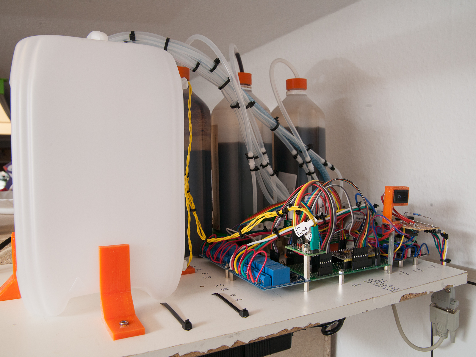
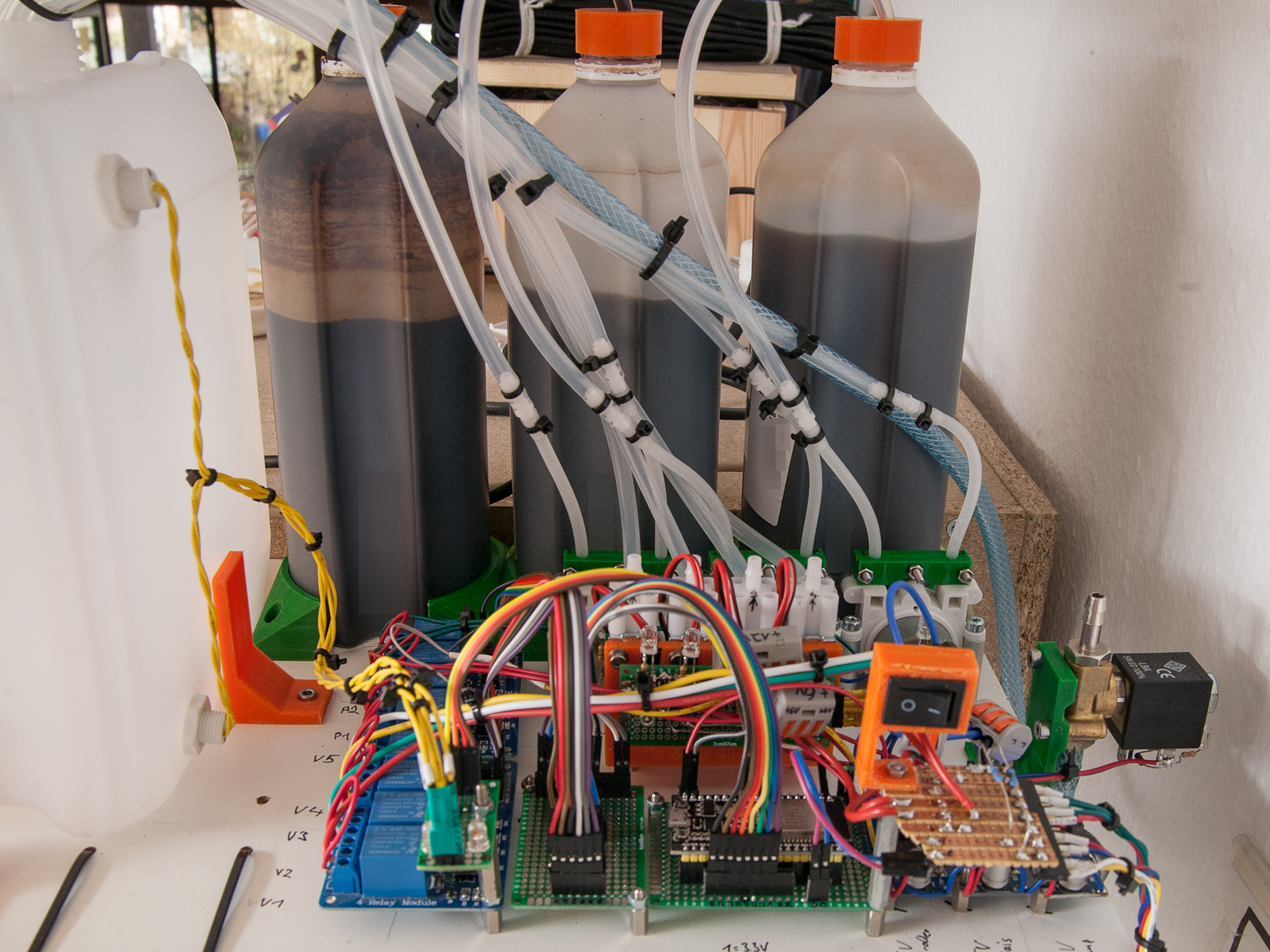
The machine consists of a 5l watertank. A solenoid valve controls the mains-water-line inlet to the tank. Small amounts of fertilizer mixture can be added to the tank using peristaltic pumps. The whole system is mounted high-up on the top of my plant shelf. That way, gravity is feeding the water from the tank to the outlets, controlled by more solenoid valves. Of course, the outlet valves can also be replaced by pumps, so everything can be mounted level, or the machine below the plants.
Even though the software uses float-switches to measure the fill-height in the tank, maximum safety timeouts are implemented for every action, so the chances of flooding the house are minimized. Still, I always manually close the mains-water-inlet with a proper hand-controlled valve after using the machine and open it only when needed, just in case!
(I'm a software developer by trade, so I'm relatively confident the software works, but I don't trust my plumbing skills too much...) 😊
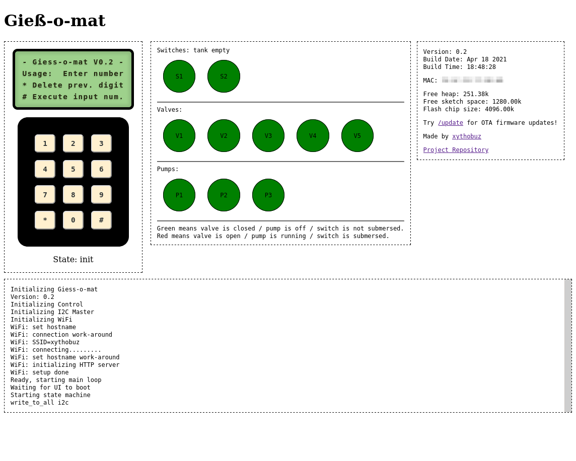
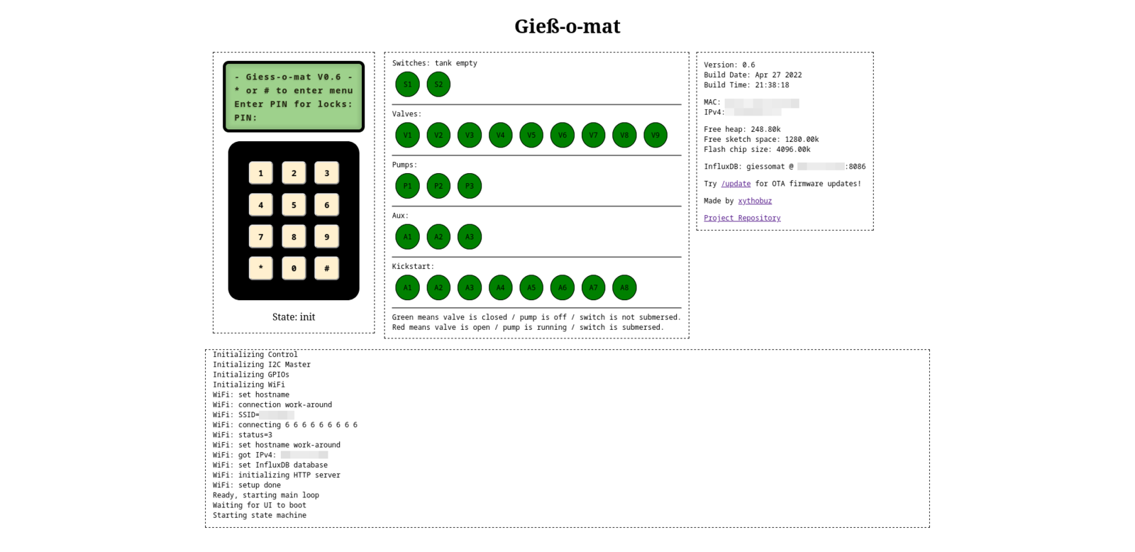
The web interface is using JS and Websockets to dynamically update the page, showing the same output that is visible on the physical display. Keypad button presses can be executed that way as well. Also, the debug logs that are normally provided on the serial port are also sent out to clients connected via the web interface.
Implementation
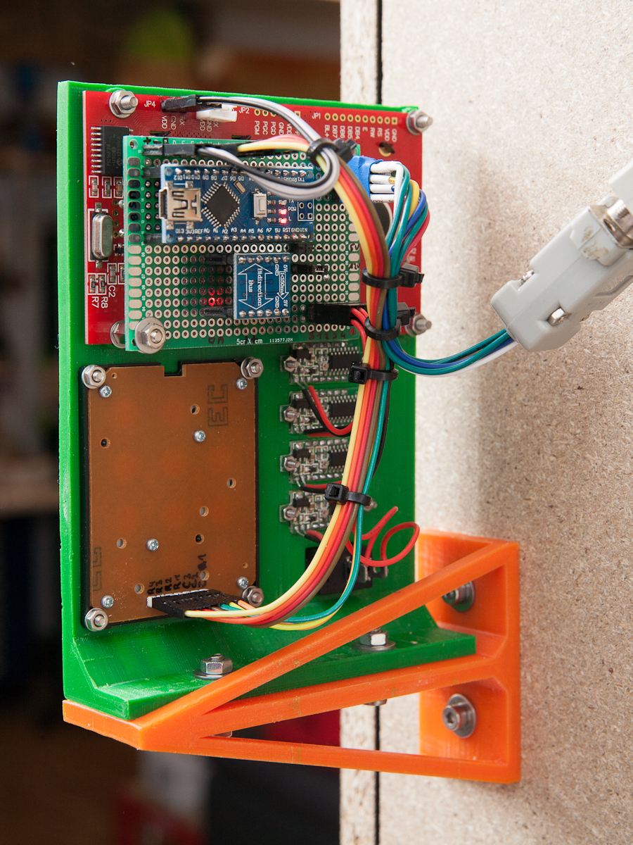
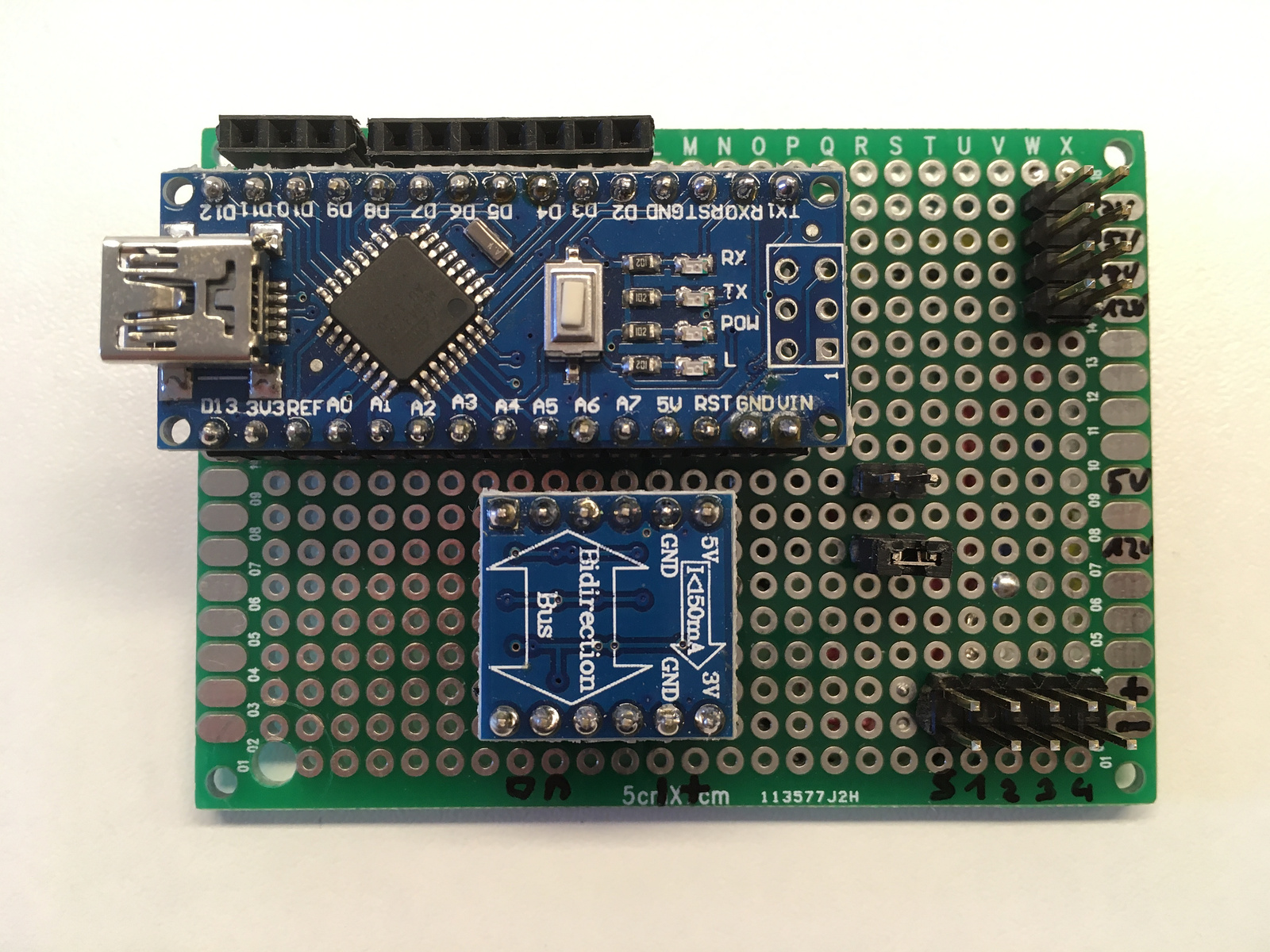
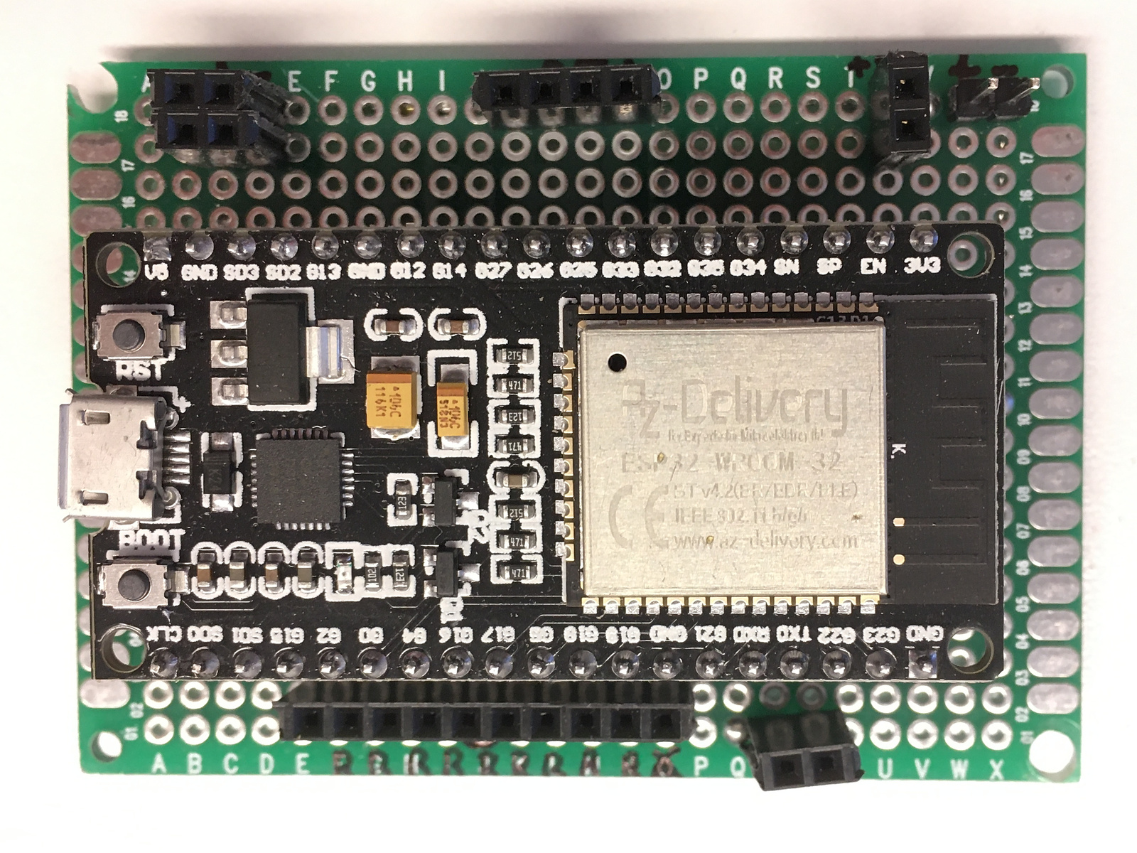
The machine is using two microcontrollers, an Arduino Nano clone and an ESP32.
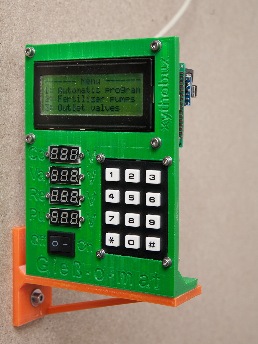
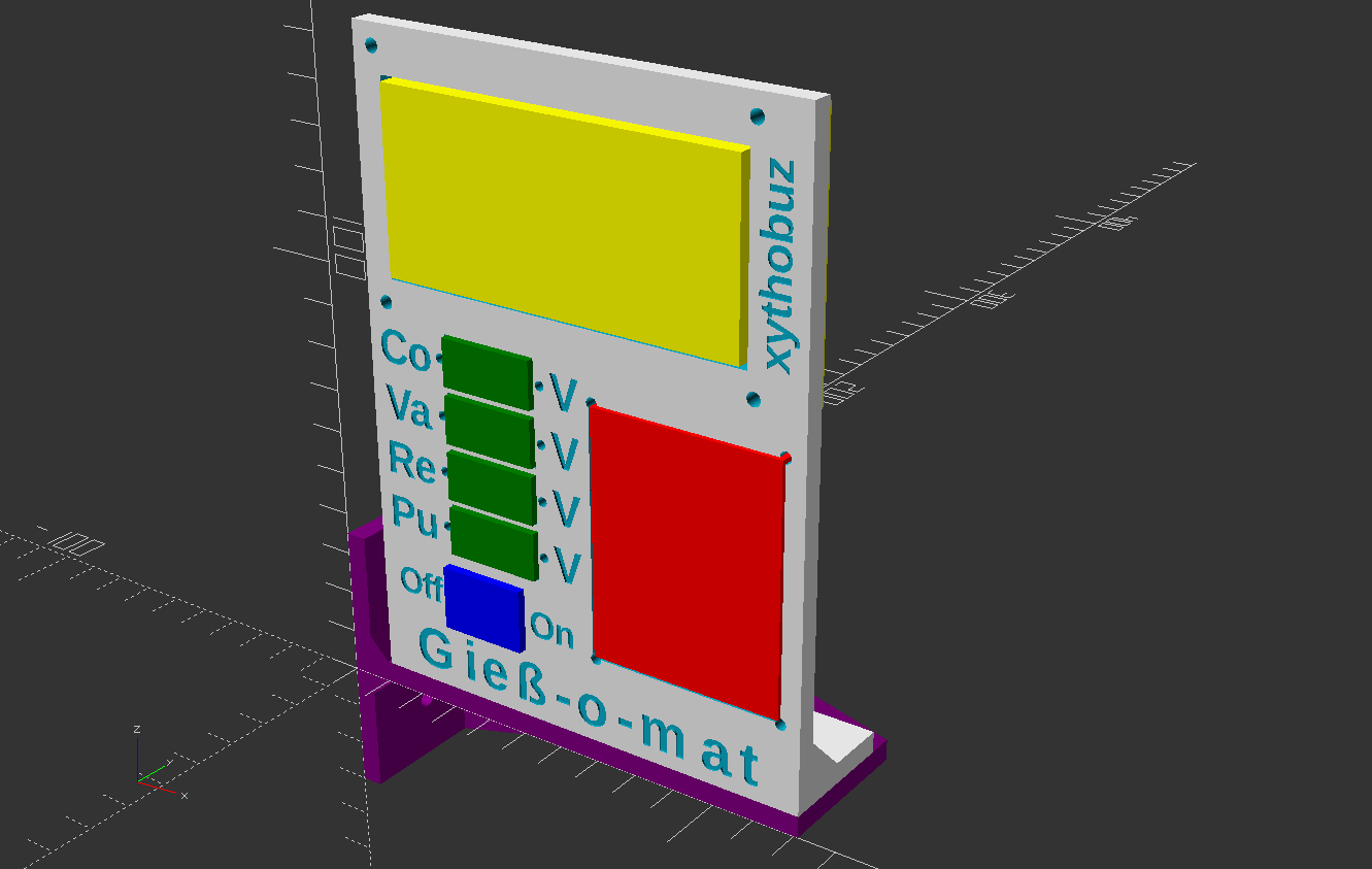
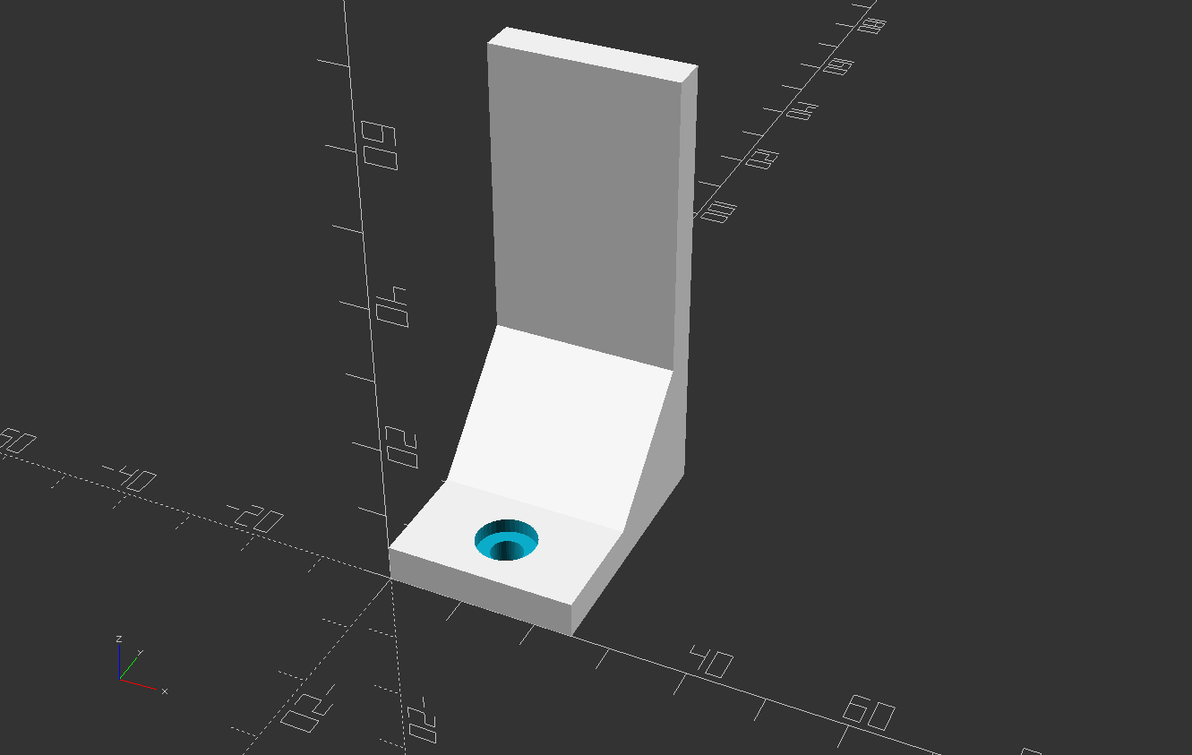
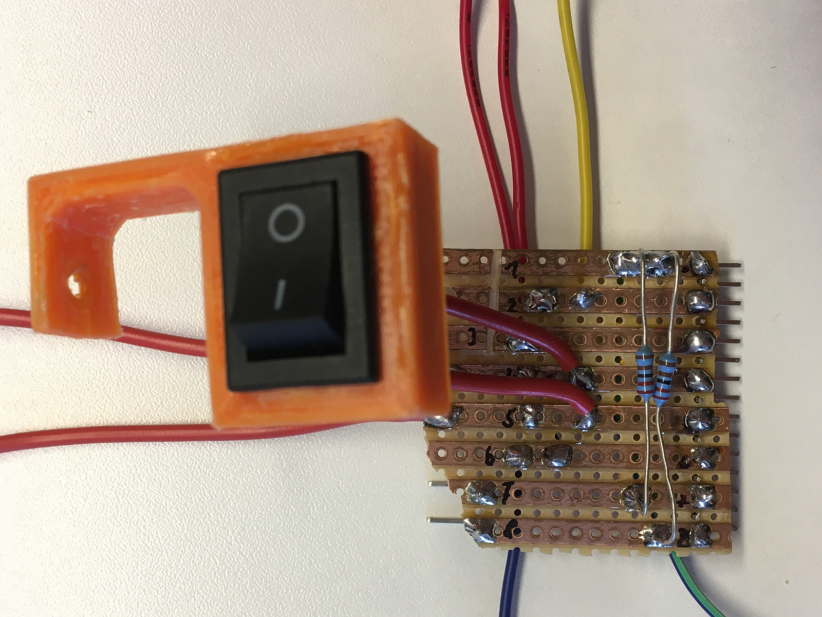
The Arduino provides the user interface, using a 20x4 LCD from a now-obsolete Sparkfun project called SerialLCD. It is connected to the Arduino via serial. Input is done using a cheap 3x4 Keymatrix directly conencted to the Arduino GPIOs. I also added a power switch and some voltmeters for the different voltage regulators and a main power switch. All this is mounted in a simple 3D-printed frontpanel.
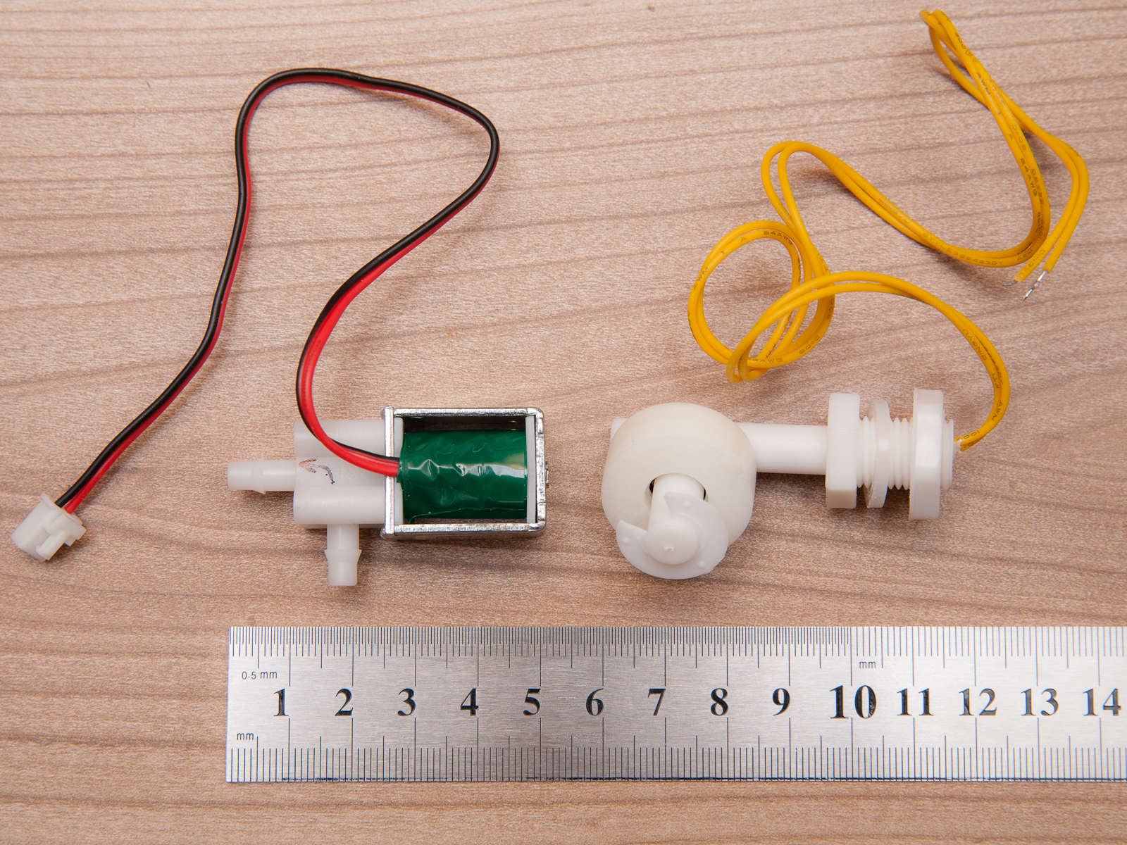
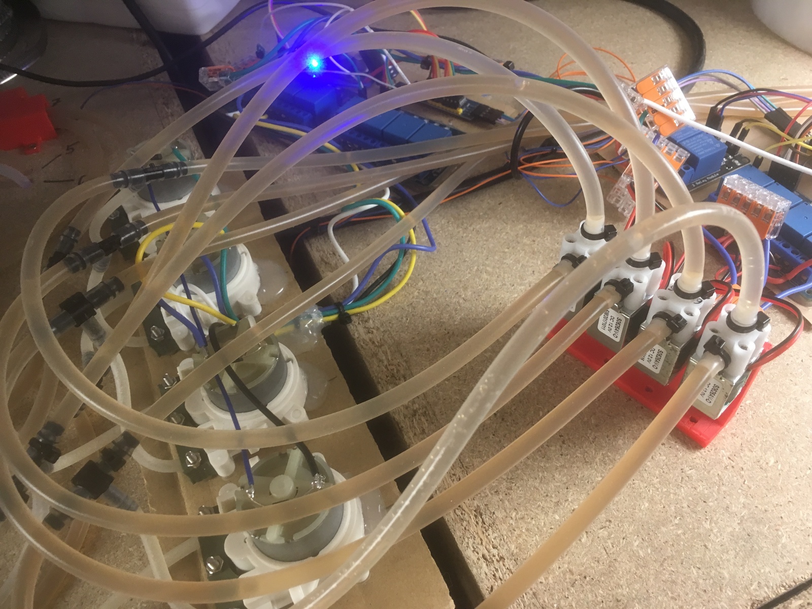
The actual control is done on an ESP32 which is connected to two 4-channel relais boards. Using these, it controls five valves (one inlet and four outlets) as well as three pumps for the fertilizers. For the outlet valves I'm using cheap small chinese solenoid valves. For the inlet, I'm using a more expensive metal solenoid valve from Germany that is able to resist the mains-water-pressure (up to 8bar) that I still had from my cocktail machine experiments. Two float switches are used to tell the fill-height of the water tank. The ESP32 also provides a simple web interface to allow the same controls as from the user interface.
Both UI and controller are connected to each other using I2C. All relevant signals are transmitted with a simple DB-9 cable.
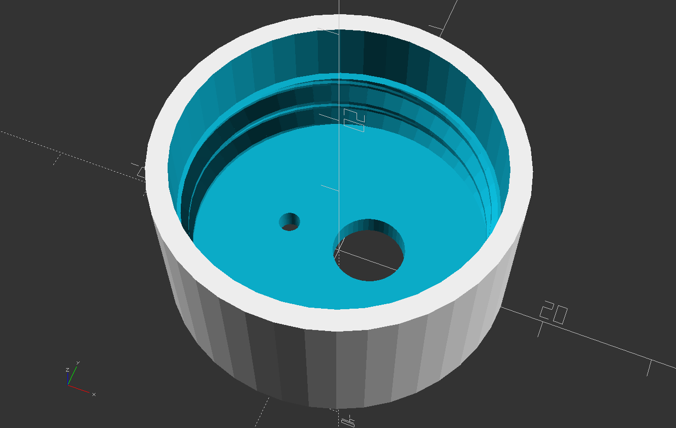
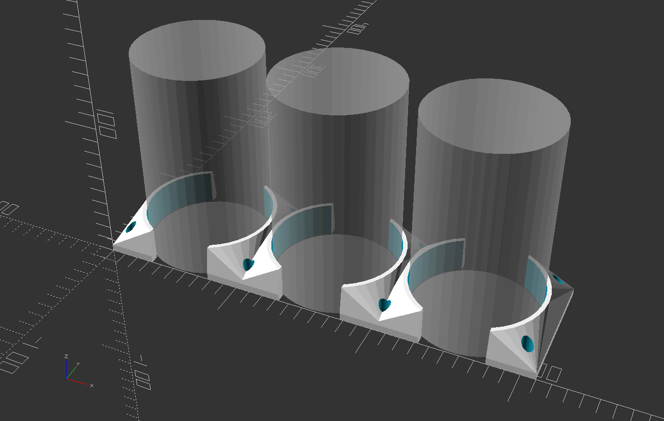
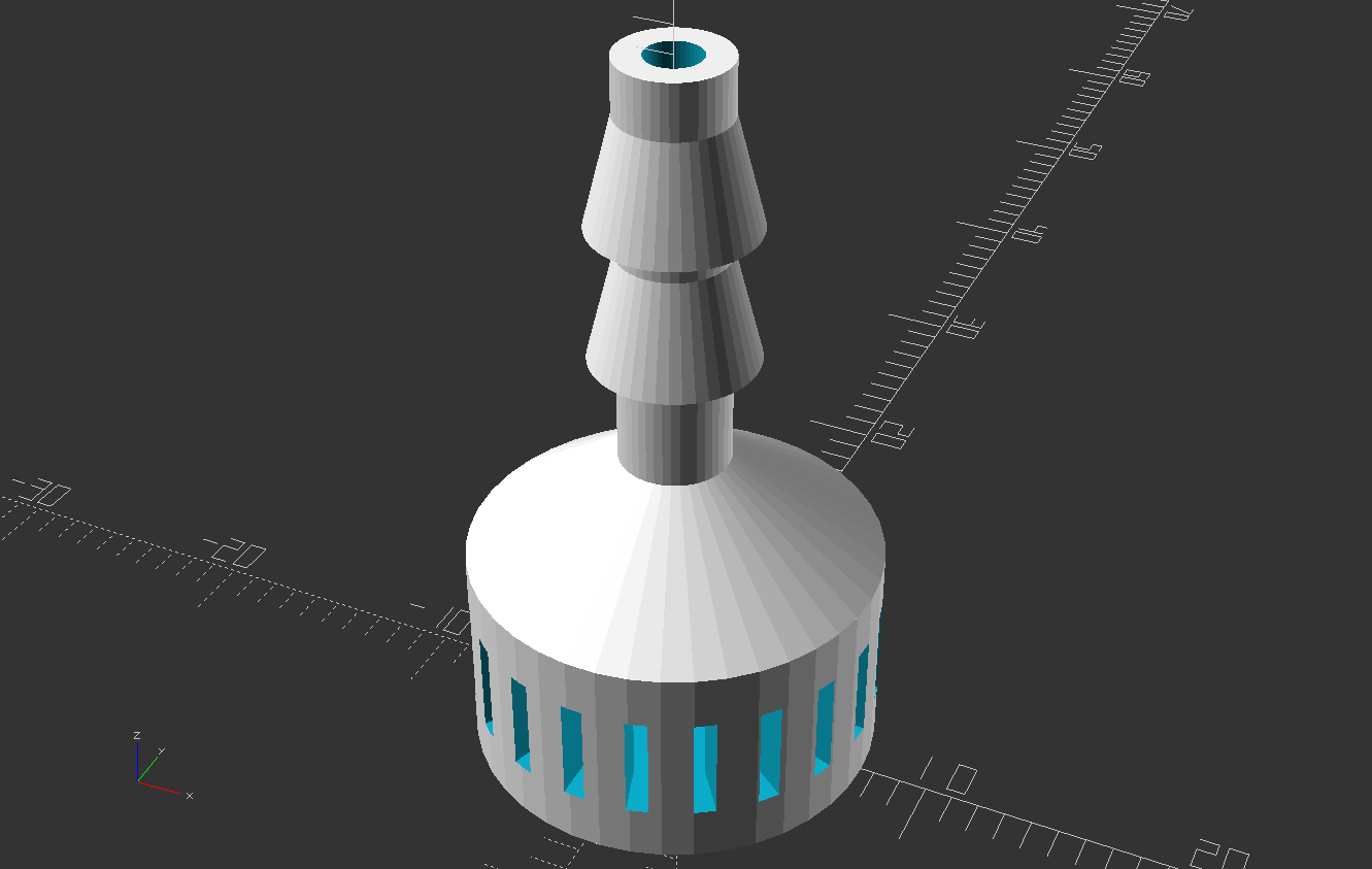
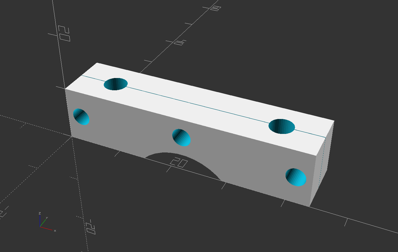
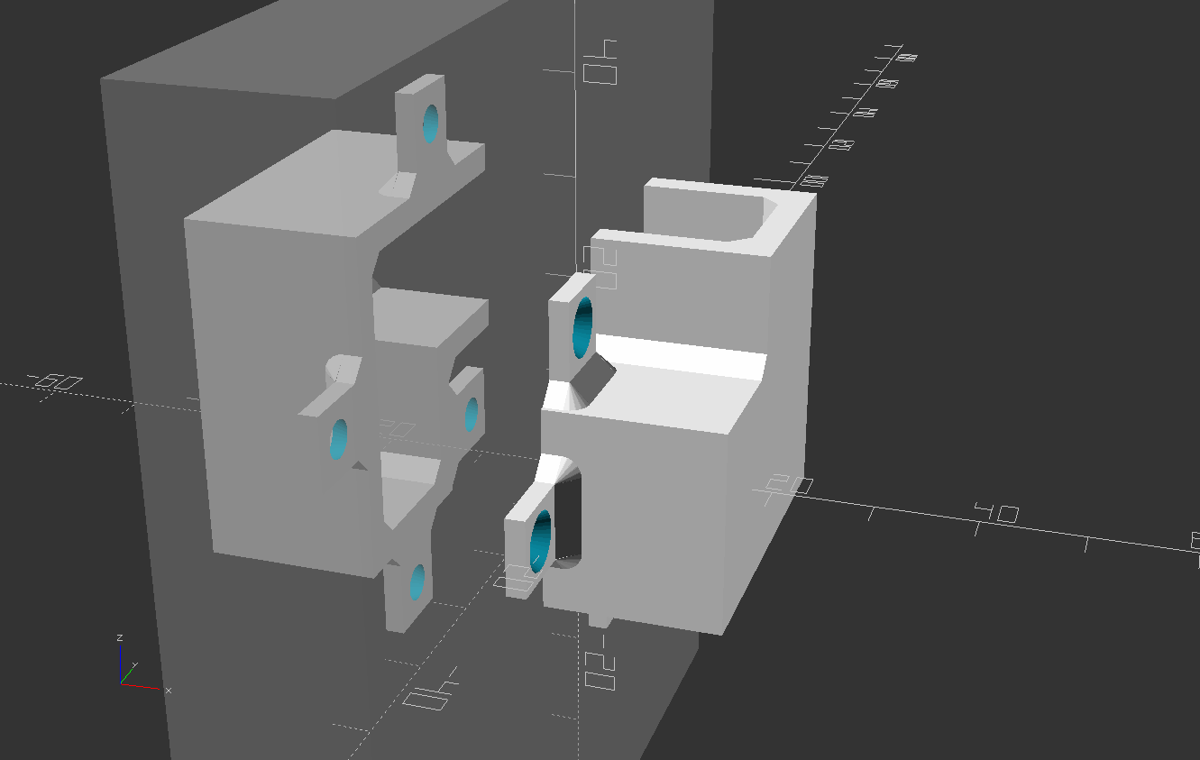
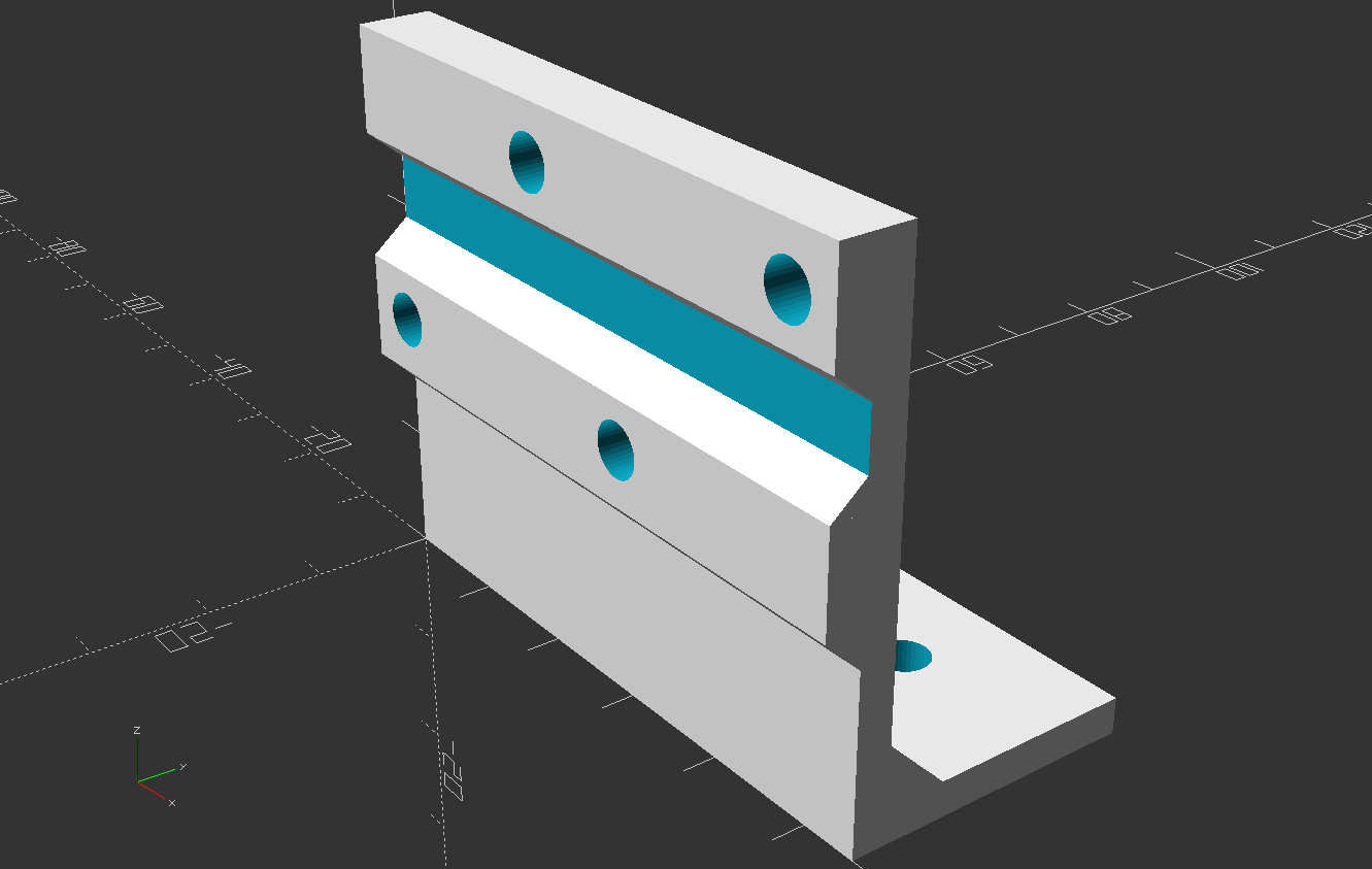
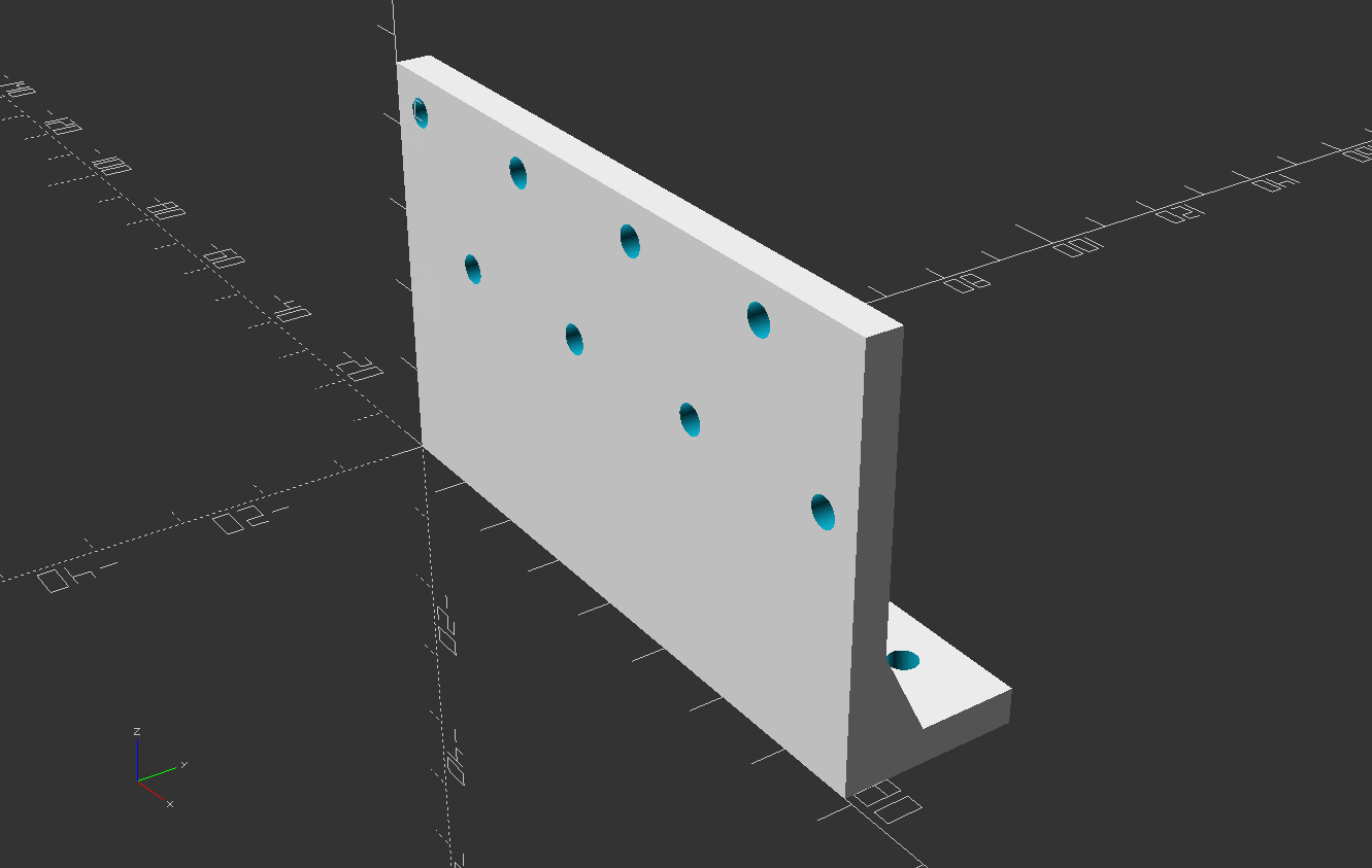
All this is mounted on an old piece of shelf-board, using some custom designed 3D printed parts. The water tank is realized using a generic 5l liquid tank, with two holes drilled for the fill switches. The holders for the fertilizer bottles, as well as the bottlecaps, are specifically designed to fit my 1l fertilizer bottles.
I designed all the 3D printed parts with OpenSCAD. You can find the files in the Git repo.
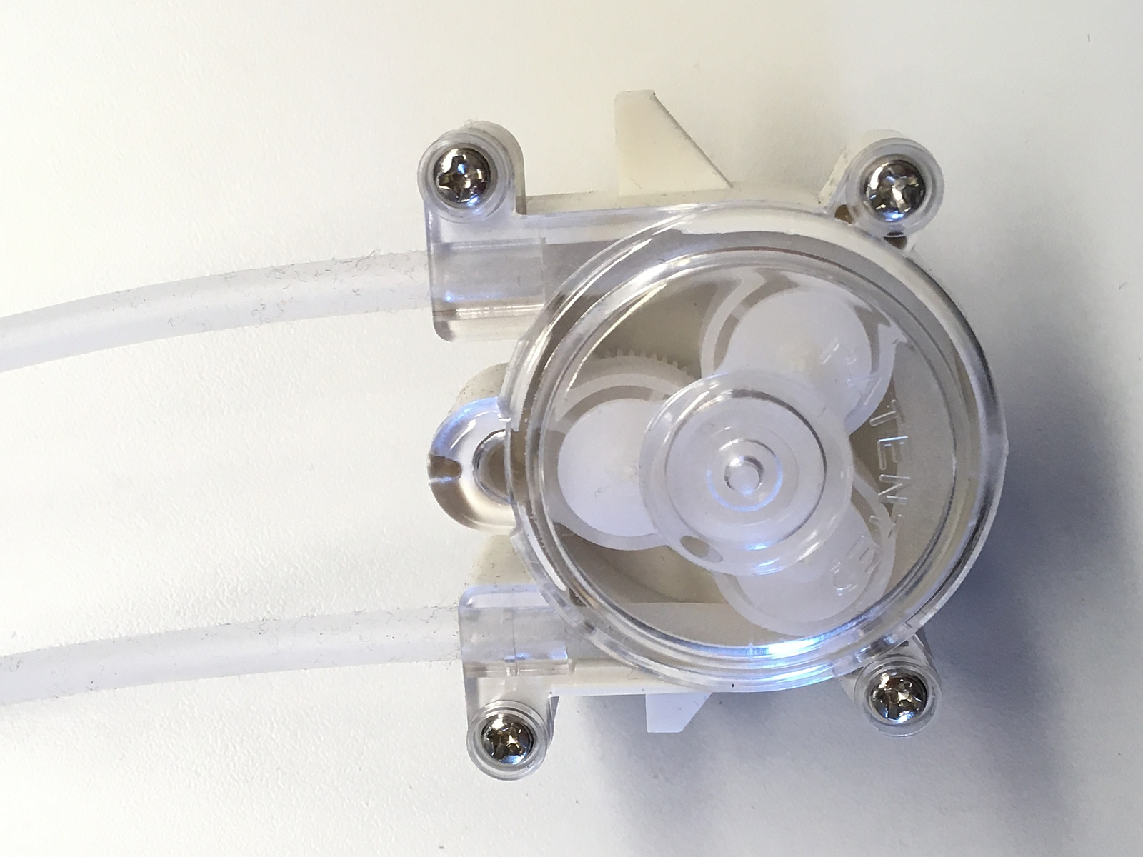
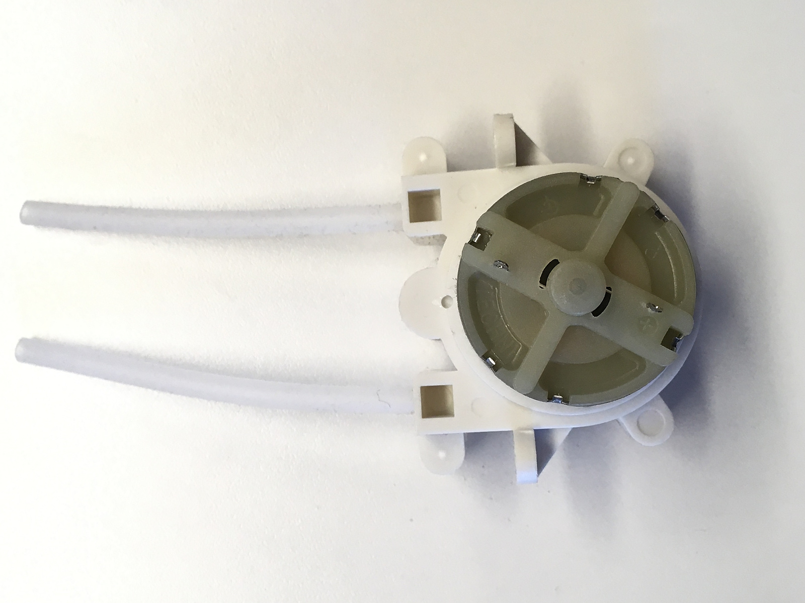
Most of the parts I had lying around in the workshop. I only had to buy the outlet valves after realizing one of the big valves I still had was no longer working. Also the pumps, hoses and hose-adapters had to be bought.
The software can easily be configured to run with more or less fertilizers and outlets, as much as the ESP32 GPIOs can provide. Alternatively, you can also use an Arduino for the controller instead of the ESP, losing the web interface. Or you can also compile the software to run both UI and control on one Arduino, as long as it has enough GPIOs for your needs (or an ESP, but I haven't tested that). You can of course also just leave out the UI and use solely the web interface on the ESP. See the README.md of the project for more details.
Doing some programming, it would also be possible to use some kind of port-extender or run also the UI on an ESP. And of course also the now-obsolete SerialLCD could be replaced with something different without too much work.
These are the circuit diagrams for the controller and user interface.
Everything is powered by a 12V 13.5V power supply.
I am using two 5V regulators, one for powering the ESP32 and one for powering the relais coils.
This was my quick-and-dirty way of getting the power rails clean enough that the ESP is not resetting when toggling a relais.
The valves are directly fed 12V 13.5V and another regulator produces 6V for the peristaltic pumps.
Giess-o-mat Controller Schematic

             -------|USB|-------                        -----------
            |       |___|       |           +13.5V <---|x IN  OUT x|---> +5V_ESP
            |  P06         +5V x|---> +5V_ESP          |  5V Buck  |
            |  P07         CMD  |              GND <---|x GND GND x|
            |  P08         P10  |                       -----------
     R5 <---|x P15         P09  |
     R6 <---|x P02         P13 x|                       -----------
     R7 <---|x P00         GND x|---> GND   +13.5V <---|x IN  OUT x|---> +5V_R
     R8 <---|x P04    E    P12 x|                      |  5V Buck  |
            |  P16    S    P14 x|---> R2       GND <---|x GND GND x|
            |  P17    P    P27 x|---> R1                -----------
     R3 <---|x P05    -    P26 x|---> SW_B
     R4 <---|x P18    3    P25 x|---> SW_T              -----------
            |x P19    2    P33 x|           +13.5V <---|x IN  OUT x|---> +6V
    GND <---|x GND         P32 x|                      |  6V Buck  |
ESP_SDA <---|x P21         P35  |              GND <---|x GND GND x|
            |  P03         P34  |                       -----------
            |  P01          SN  |
ESP_SCL <---|x P22          SP  |                        -------
            |x P23          EN  |            +13.5V <---|x +12V |
    GND <---|x GND        +3V3 x|---> +3V3  ESP_SDA <---|x SDA  | UI
            |                   |           ESP_SCL <---|x SCL  | Conn.
             -------------------                GND <---|x GND  |
                                                         -------

           ---------------------                       ---------------------
          |        Relais       |                     |        Relais       |
  GND <---|x GND    ----   NC1 x|             GND <---|x GND    ----   NC1 x|
   R1 <---|x R1    |    | COM1 x|---> +13.5V   R5 <---|x R1    |    | COM1 x|---> +13.5V
   R2 <---|x R2     ----   NO1 x|---> V1       R6 <---|x R2     ----   NO1 x|---> V5
   R3 <---|x R3     ----   NC2 x|              R7 <---|x R3     ----   NC2 x|
   R4 <---|x R4    |    | COM2 x|---> +13.5V   R8 <---|x R4    |    | COM2 x|---> +6V
 +3V3 <---|x VCC    ----   NO2 x|---> V2     +3V3 <---|x VCC    ----   NO2 x|---> P1
          |         ----   NC3 x|                     |         ----   NC3 x|
          |        |    | COM3 x|---> +13.5V          |        |    | COM3 x|---> +6V
          |         ----   NO3 x|---> V3              |         ----   NO3 x|---> P2
          |         ----   NC4 x|                     |         ----   NC4 x|
          |        |    | COM4 x|---> +13.5V          |        |    | COM4 x|---> +6V
          |         ----   NO4 x|---> V4              |         ----   NO4 x|---> P3
          |x VCC                |                     |x VCC                |
+5V_R <---|x JC-VCC             |           +5V_R <---|x JC-VCC             |
           ---------------------                       ---------------------

  GND <--------------> Float Switch 1 COM     GND <--------------> Float Switch 1 COM
 SW_B <--------------> Float Switch 1 NO     SW_B <--------------> Float Switch 1 NO
          |      |                                    |      |
         ---     |                                   ---     |
     LED / \-->  |                               LED / \-->  |
         ---     |                                   ---     |
          |      |                                    |      |
         ---    ---                                  ---    ---
        |   |  |   |                                |   |  |   |
     1k |   |  |   | 1k                          1k |   |  |   | 1k
        |   |  |   |                                |   |  |   |
         ---    ---                                  ---    ---
          |      |                                    |      |
        +3.3V ---                                   +3.3V ---
Giess-o-mat User Interface Schematic

            -------|USB|-------
           |       |___|       |
           |x D13         D12 x|                         Level Conv.
           |x 3V3    A    D11 x|                         -----------
           |x REF    R    D10 x|---> LCD_TX  +5V_UI <---|x 5V   3V x|
           |x A0     D     D9 x|                GND <---|x GND GND x|
           |x A1     U     D8 x|---> KP_R4   SDA_UI <---|x D5   D3 x|---> ESP_SDA
           |x A2     I     D7 x|---> KP_R3   SCL_UI <---|x C5   C3 x|---> ESP_SCL
           |x A3     N     D6 x|---> KP_R2               -----------
SDA_UI <---|x A4     O     D5 x|---> KP_R1
SCL_UI <---|x A5           D4 x|---> KP_C3               Connector
           |x A6           D3 x|---> KP_C2                -------
           |x A7     N     D2 x|---> KP_C1    +13.5V <---|x +12V |
+5V_UI <---|x 5V     A    GND x|---> GND     ESP_SDA <---|x SDA  |
           |x RST    N    RST x|             ESP_SCL <---|x SCL  |
   GND <---|x GND    O     RX x|                 GND <---|x GND  |
+13.5V <---|x VIN          TX x|                          -------
           |                   |
            -------------------                  ----------
                                    ESP_SDA <---|   2.2k   |---
            KP_C1 KP_C2 KP_C3                    ----------    |--> 3.3V
              |     |     |         ESP_SCL <---|   2.2k   |---
           -------------------                   ----------
          |  ---   ---   ---  |
KP_R1 <---| | 1 | | 2 | | 3 | |                 --------------------------
          |  ---   ---   ---  |     +5V_UI <---|x VCC                     |
          |  ---   ---   ---  |     LCD_TX <---|x RX                      |
KP_R2 <---| | 4 | | 5 | | 6 | |        GND <---|x GND                     |
          |  ---   ---   ---  |                |   --------------------   |
          |  ---   ---   ---  |                |  |                    |  |
KP_R3 <---| | 7 | | 8 | | 9 | |                |  |         LCD        |  |
          |  ---   ---   ---  |                |  |        20x4        |  |
          |  ---   ---   ---  |                |  |                    |  |
KP_R4 <---| | * | | 0 | | # | |                |   --------------------   |
          |  ---   ---   ---  |                |                          |
           -------------------                  --------------------------
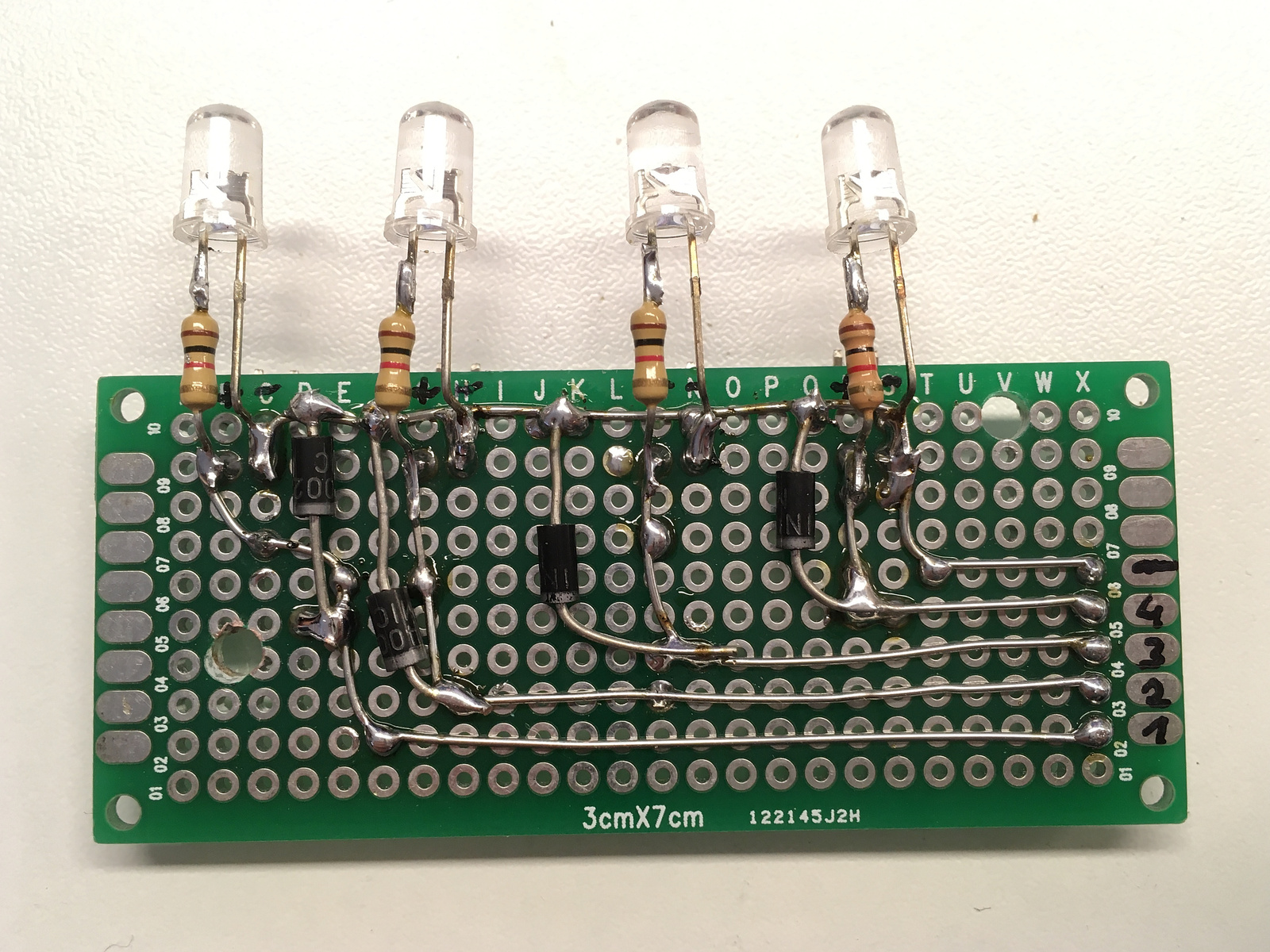
As you can see, the schematic is relatively simple, not doing much more than connecting some modules with each other. I did not (have to) add any kind of filtering or other passive circuitry. The only exception are flyback diodes for all inductive loads connected after the relais. They are not included in the schematics, so don't forget to add appropriate ones, depending on the exact valves you use.
On the schematic above, only the four required connections between controller and user interface are shown. I have used a DB-9 connector, running the power switch as well as the other voltages generated on the controller over it. This is so the machine can be turned on and off at the UI. I also placed some cheap little voltmeter modules on the UI, showing the other voltages.
Future Extensions (v1)
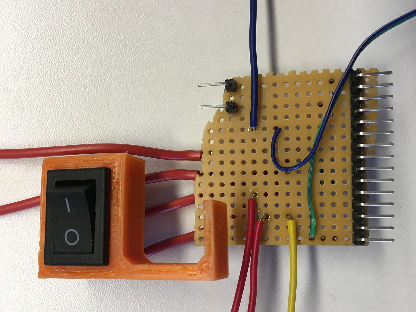
I have now been running capacitive ground moisture level sensors in a couple of my plants for around a year, logging the data using my ESP-Env project to an InfluxDB instance running on my NAS, with a Grafana UI running on there as well. I used the cheap chinese models up to now, and they have not proven very useful. They of course don't corrode as fast as the resistive-measurement-based sensors, but they still age because of the permanent water contact. I tried to work-around that by using Plastik70 in liberal amounts with multiple coatings on the sensor, but even with that they show quite considerable drift over a couple of months. The data is good enough to see when I watered the plants, but it is difficult to determine a value where automatic watering should occur. Because of that, I have not yet added completely automated watering into the system. It still has to be started manually via the user interface.
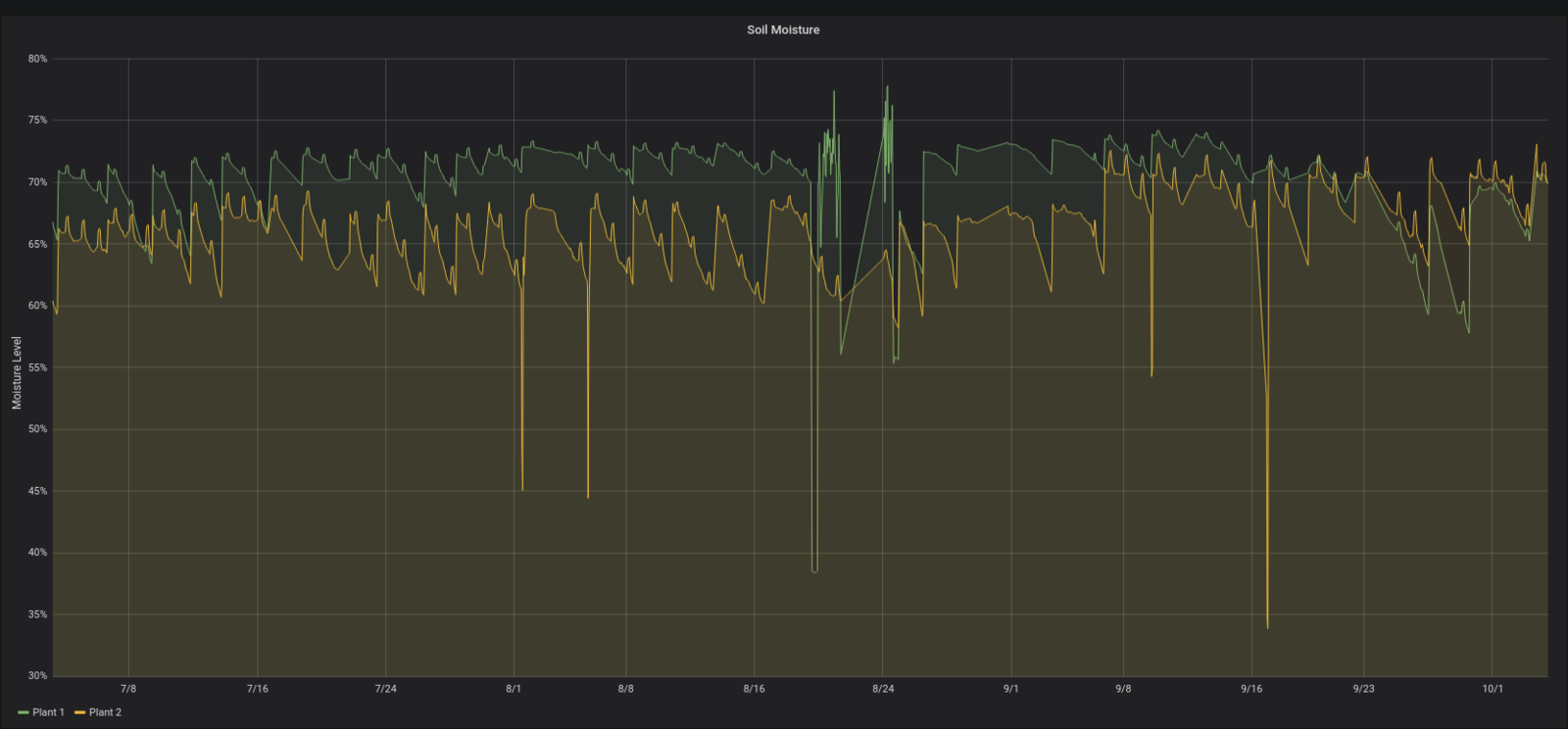
If you look closely you can also see some glitches in the data where my ESP had problems and did not store new values. Also consider that in the timeframes seen in the graph above, I always watered the plants manually as soon as the soil felt dry about 3cm deep.
But recently I got a different sensor from a colleague of mine, which is from another project called Giesomat. The similar name was totally incidental, I only heard of it after naming my own project like this. I will test it and report the results here sometime in the future.
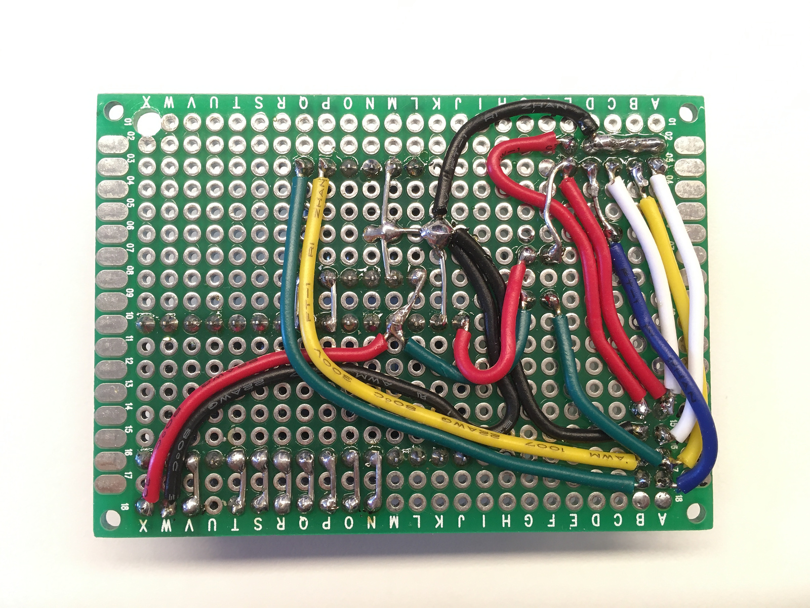
Also, it would of course be possible to design a custom PCB for the hardware. But to be quite honest, I don't see the appeal in that currently. It would lose the ability to use a different number of pumps and valves, as needed by the specific application. And building all this up on perf-boards is really not much work.
Fertilizer Update (June 2021)
After using the first version of this project for a while, I noticed some problems with the different fertilizers I'm using.
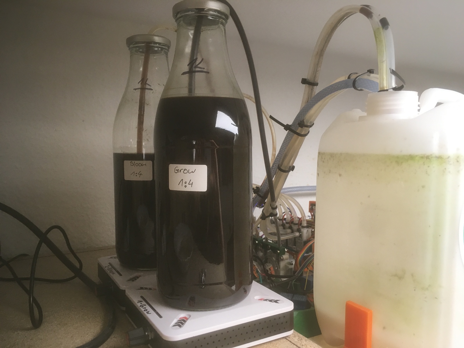
The set of fertilizers I like to use consists of three parts, for different stages of the lifecycle of the plants and different requirements for different species. They differ in their contents, and also in the viscosity, from thick to thin.
The third, thinnest, fertilizer pumps easily with my initial setup. Even when not using it for a while, the liquid simply stays in the hose, held against gravity by the inactive pump. For the next use, the pump simply can be started and immediately starts dispensing.
Unfortunately, for the other two thicker fertilizers this does not work. As you can see in the example video linked above, they move much slower and take more work from the pump. But they also have a higher level of NAK and solid contents. This is not a problem initially, but after being held in the hose for a while, the nutrients in the fertilizer crystallize and completely block the hose. If the wait was short enough, the pump can overcome the obstacle and push it out and crush it, but you have to be lucky for that. After a short time, the pumps no longer move anything at all.
Additionally, the solid contents settle at the bottom of the bottles. For hand-use, that is not a problem, you simply shake the bottle before use. But automating this takes some more work.
To solve these issues, I initially thought about modifying the circuitry, using a dual H-Bridge motor driver to control the pumps of the problematic fertilizers. This way, the direction of the pump can be reversed to empty the hose. For this to work, of course the water level in the tank needs to be below the outlet level of the fertilizer hoses. But this can be achieved easily by shortening the hoses a bit. Then the hose can be completely emptied afer dispensing the required amount of liquid. Of course, the pump now needs to run longer to fertilize, as the liquid has to travel the length of the hose each time. But it should solve the crystallization issue.
But before going this way, I decided to try diluting the fertilizer with water. In this case, the pumps need to run longer of course, but this is not a problem. It seems to work fine, regarding the crystallization problem, for now.
For the solid contents settling, I bought two cheap chinese magnetic stirrers. The bottles need relatively flat bottom surfaces and they need to be positioned well on the stirrer, but they have enough power to move the rotor and stir even the thickest of my fertilizers. The stirrers run on 12V and can simply be connected to another relais.
Automation Update (October 2021)
As mentioned above, I'm running InfluxDB in my home network. To be able to implement an automated watering feature more easily, I decided to use the database. The plan is to record usage data for a couple of months, which can then be analyzed by a script that generates the parameters for the watering timer. I have been running this for a while already, but I only recorded the runtime of the water in seconds. The data already shows differing flowrates for the different outlets. This is because some plants are higher up then others, causing less pressure differential and therefore reduced flow velocity.
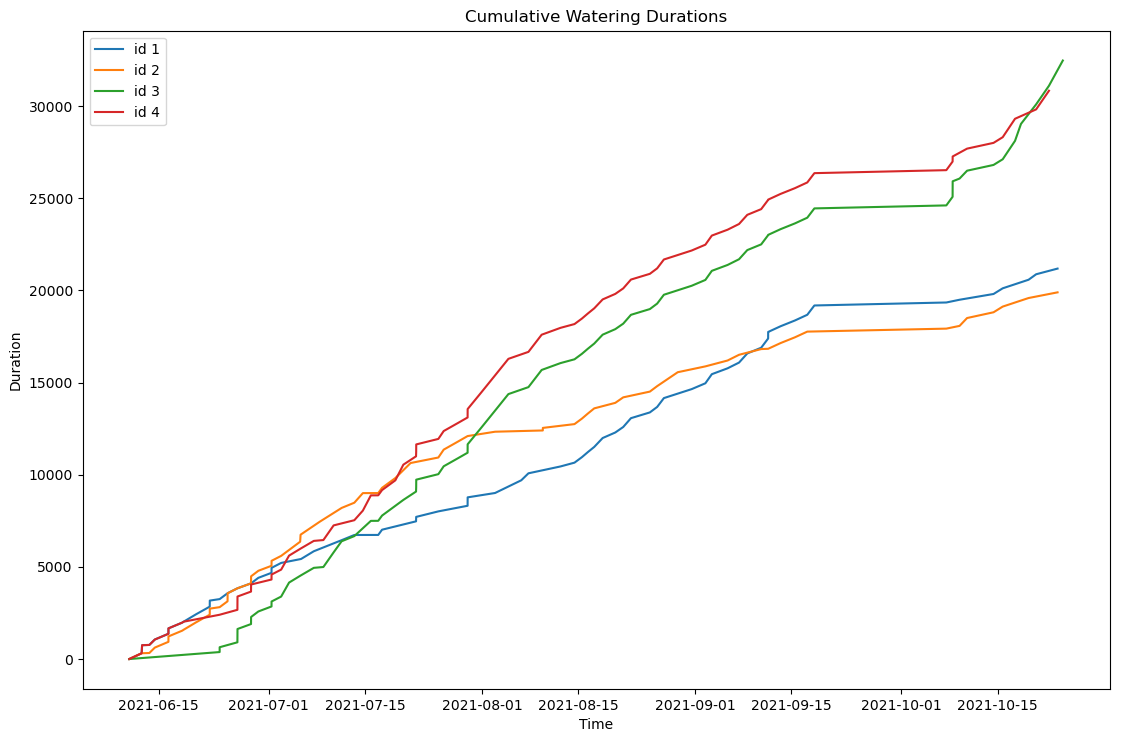
I now added some more code to be able to calibrate the flowrates. With this the exact water amounts required each watering period can be calculated, as well as the corresponding time to fill the tank. More to come in the future.
Moisture Sensor Update (November 2021)
After taking a closer look to my soil moisture sensors, with the help of the investigation by Stewart Cash, I found some issues with the cheap chinese sensors I used.
The 1M resistor is actually properly connected to GND on my boards. However, mine have an NE555 IC fitted, which requires 5V. On some of the boards I have, the 3V regulator is still fitted, on some others it has been replaced with a 0 Ohm link. However, I was trying to power them using the 3.3V rail of my ESP32. With 5V they now output a nice signal when placing them directly in or out of a glass of water.
Placing them back in the soil, they no longer seem to output much of a signal at all, anymore, only giving a relatively straight line. I'm not sure what's going on this time. Further experiments to come (maybe).
Chinese Magnetic Valve Update (November 2021)
After a bit more then half a year of daily use, one of the four outlet valves has started to act up. It no longer opened up completely, letting only a small dribble of water out. I opened the valve, saw a bit of limestone, and cleaned the plunger. This helped for a short while, but the problems returned only a short while later.
With a bit more investigation I found the cause: the supply voltage was too low. I was initially using a 12V power supply to drive the whole device and the vales. But because of cable losses, and high current use of the valves, only about 11.4V arrived at the valve. It turns out this is just low enough that, together with the increased friction of the scale buildup, the valve no longer opens properly.
See the two videos below.
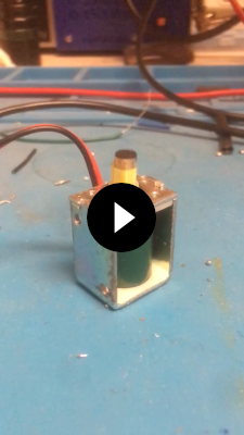
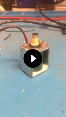
For a work-around, I simply replaced the power supply, now driving everything with 13.5V instead of 12V. This seems to solve the issue for now.
GPIO Expansion / Door Lock Update (February 2022)
After a year of operating the Gieß-o-mat the time came to expand it with some more outlets. Because unused GPIOs on the ESP32 are starting to run out, I decided to try and add an I2C GPIO expansion for more relais.
For this I used the PCF8574, which I already used in the past, but can now be bought easily on nice little breakout boards. As before, I added some relais modules to drive four more outlet solenoid valves. As mentioned above, take care to add flyback diodes to all inductive loads (for the relais inductors, these are already included on the modules).
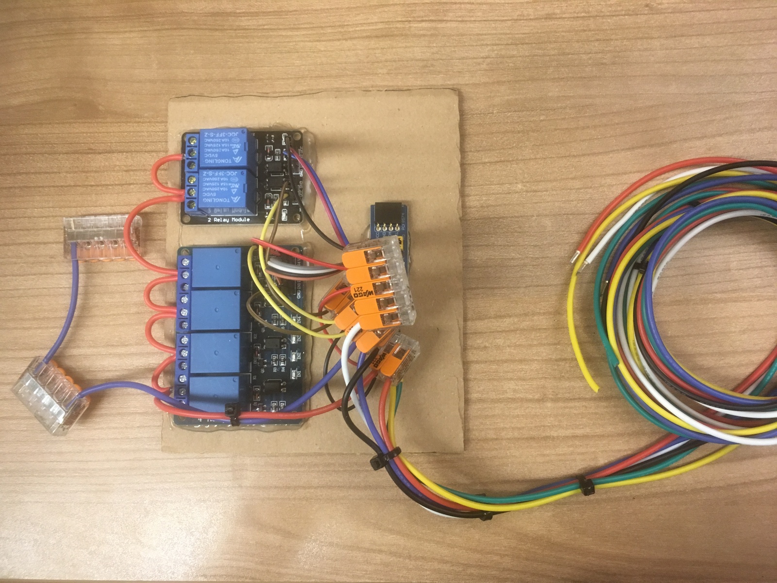
Unfortunately, the breakout modules don't contain any filtering capacitors. Because of the long cable length to the expansion, as well as the relatively high power requirements of the loads, I had some issues with the power supply at the expansion. The ESP itself ran fine, only the PCF8574 saw a voltage glitch large enough that it resets. This caused the relais to try to turn on for a very brief time (milliseconds), immediately causing the supply voltage to the PCF to fall, which resets and then turns the relais off again.
Adding liberal amounts of filtering capacitors (330µF) to all three power rails going to the expansion (12V, 5V, 3.3V), as well as more caps directly at the PCF module (3900µF), helped enough to completely fix the issue.
Giess-o-mat I2C GPIO Expansion Schematic

              --------
  +13.5V <---|x +12V  |
   +5V_R <---|x +5V_R |
    +3V3 <---|x +3V3  |
 ESP_SDA <---|x SDA   |
 ESP_SCL <---|x SCL   |
     GND <---|x GND   |
              --------

           ---------------------
          |        Relais       |
  GND <---|x GND    ----   NC1 x|
   R1 <---|x R1    |    | COM1 x|---> +13.5V
   R2 <---|x R2     ----   NO1 x|---> V6
   R3 <---|x R3     ----   NC2 x|
   R4 <---|x R4    |    | COM2 x|---> +13.5V
 +3V3 <---|x VCC    ----   NO2 x|---> V7
          |         ----   NC3 x|
          |        |    | COM3 x|---> +13.5V
          |         ----   NO3 x|---> V8
          |         ----   NC4 x|
          |        |    | COM4 x|---> +13.5V
          |         ----   NO4 x|---> V9
          |x VCC                |
+5V_R <---|x JC-VCC             |
           ---------------------

              -----------------
    +3V3 <---|x VCC   P   IO1 x|--> R1
     GND <---|x GND   C   IO2 x|--> R2
 ESP_SDA <---|x SDA   F   IO3 x|--> R3
 ESP_SCL <---|x SCL       IO4 x|--> R4
             |        8   IO5 x|
             |        5   IO6 x|
             |        7   IO7 x|
             |        4   IO8 x|
              -----------------

        330µF                    330µF
+3V3 <---||---> GND    +13.5V <---||---> GND
       |    |
        -||-            +5V_R <---||---> GND
       3900µF                    330µF
Below you can see some screenshots I took on my scope.
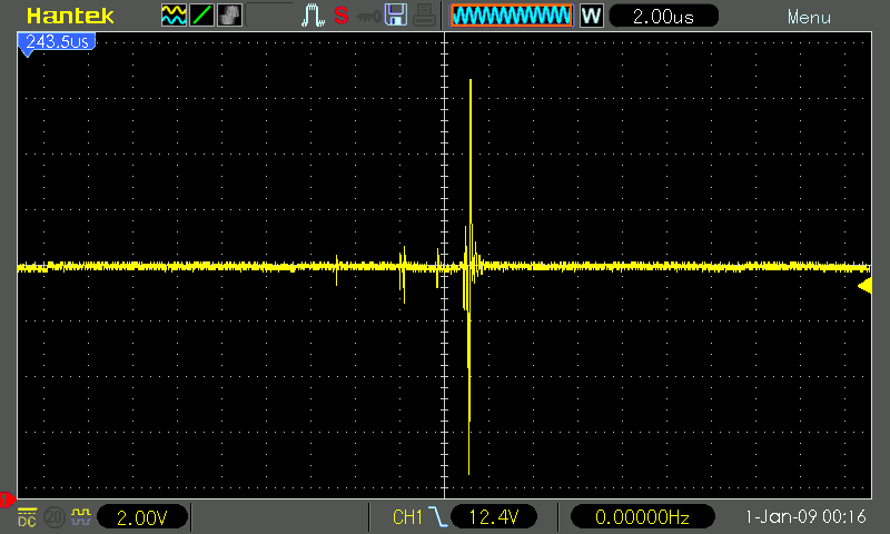
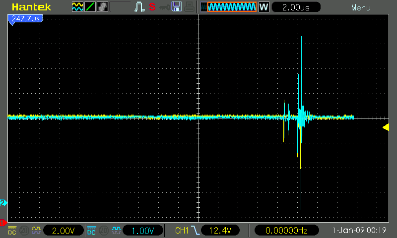
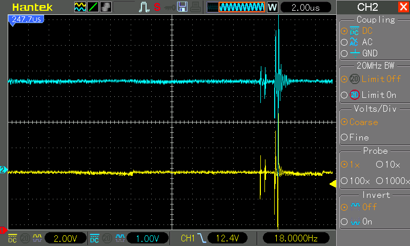
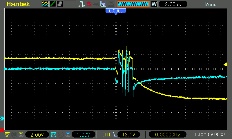
CH1 (yellow) is the 12V rail, CH2 (blue) is the 3.3V rail. In the first three screenshots you can see the glitch caused by switching on one of the loads at the GPIO expansion. The 12V rail goes down to about 5V and up to 19V. The 3.3V rail, at the same time, even goes slightly below 0V and up to nearly 7V. To be honest, I'm surprised nothing died in these experiments. On the last screenshot, with some filtering in place, you can see that the relais now keeps turned on, with the load dropping the 12V rail to about 8V. The last screenshot was still missing the 3900µF on the 3.3V rail, and there were still some problems then.
Recently bigclivedotcom reviewed chinese door lock solenoids. I ordered some as well and added them to my "greenhouse" doors. Because they pull a lot of current, I had to use another separate 12V power supply.
The software has been updated to now support 16 I2C GPIO expanders with 8 pins each, for all supported functions (valves, pumps, stirrers, locks). To unlock the doors I added an optional PIN entry function on the start screen of the UI.
Valve Kickstarting Update (March 2022)
Right at the beginning, another issue came up with the machine. The gravity-fed outlet valves work fine as planned, as long as the whole length of the outlet hose is primed / filled with water. Then, all the water in the lower part "pulls" downward from gravity, creating a negative pressure differential that sucks the liquid out of the tank. Unfortunately, with enough time between dispensing water, the hose starts slowly emptying into the plant. After enough time passes, all the water up to the highest point of the hose has flowed out. When then trying to dispense more water, nothing happens when opening the valve. The way I worked around that was by using a syringe to suck some air out of the bottom of the hose, at the plants. Not much is needed, only enough to bring the water below the height of the inlet in the tank.
This was passable at the beginning. I am physically present at the machine anyway to tell it to start dispensing, so quickly priming the valves was not that much more work. But as the project matures, I'd like to use it to further automate the plant watering, so I had to find a way to fix this problem.
The solution comes in the form of more pumps, one connected "in parallel" to each outlet valve. This way, the pumps can run for a couple of seconds at the beginning, to "kick start" the water flow. But because they are pretty noisy, they turn off after 10sec, after which the valves take over with gravity.
To connect the pumps, I used more I2C port expanders with relais, as described in the GPIO Expansion Update above.
The software has been updated to allow setting optional kickstart pins for each outlet valve.
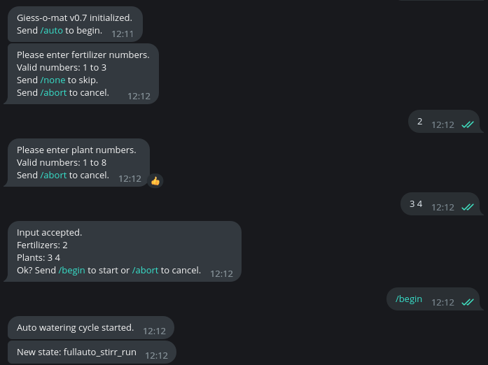
Full-Auto mode and Web-UI tweaks (May 2022)
The next step in automating the workflow is the "Full-Auto mode". This allows the user to enter the required fertilizers and plants at the beginning. The machine then first stirrs the fertilizers, dispenses them as needed, fills the tank, waters the plants, clears the tank from water, fills the tank again with a bit of clean water, empties that and finally lets the hoses run empty.
This not only reduces user-interaction, only requiring button presses at the start of the operation. It also reduces the possiblity of fertilizer-water-mixture remaining in the hoses and tank, which causes algae growth. Running the hoses empty only works when kickstart pumps are added to each valve, of course.
While doing this, I also slightly re-designed the web interface, reducing the size of the graphical indicators, so more fit on the screen.
Telegram Bot and MQTT API (November 2022)
With increasing confidence in my machine I decided to add the ability to trigger watering cycles from external sources. The initial idea was to implement a Telegram bot that has a simple interface to trigger a "full-auto cycle" (described above). I did that using the Universal-Arduino-Telegram-Bot library. Unfortunately it really takes a long time to poll for new messages, between one and two seconds. Because I don't really use interrupts and handle all timings of valves and pumps in a busy-loop that also polls all available input methods, this causes quite noticable delays in both the UI as well as the timing of operations.
My friend Philipp suggested I should use the AsyncTelegram2 library instead, which I did. This greatly reduces the overhead of polling for new messages, so there is no noticeable impact on the UI and functionality.
I then also quickly whipped up a MQTT API using the pubsubclient library. This has no poll timing problems, but of course it's also not possible to reach from outside my home network without some kind of VPN or so.
$ mosquitto_pub -h SERVER_IP -u MQTT_USER -P MQTT_PASS -t giessomat -m "auto 2 1,2"
Links
You can find all the source code for the device itself (both the UI and the Controller) as well as the OpenSCAD design files for the 3D printed parts in their Git repos. The project is also mirrored on GitHub.
License
Giess-o-mat is licensed under the GNU General Public License.
Copyright (c) 2021 Thomas Buck <thomas@xythobuz.de>

Giess-o-mat is free software: you can redistribute it and/or modify
it under the terms of the GNU General Public License as published by
the Free Software Foundation, either version 3 of the License, or
(at your option) any later version.

Giess-o-mat is distributed in the hope that it will be useful,
but WITHOUT ANY WARRANTY; without even the implied warranty of
MERCHANTABILITY or FITNESS FOR A PARTICULAR PURPOSE.  See the
GNU General Public License for more details.

You should have received a copy of the GNU General Public License
along with Giess-o-mat.  If not, see <https://www.gnu.org/licenses/>.

