OpenChrono
Airsoft Chronograph and Tracer Unit made with Arduino and 3D Printing
Project published on June 26, 2022.Last updated on July 07, 2022.
Recent activity in the repo: 
Over the past years I've been kinda getting into gas-driven Airsoft guns. They are interesting from a technical perspective and they are fun toys, as well! 😊
Of course it didn't take much time for me to get some ideas on how to combine this with my other interests. So I decided to build a chronograph that can measure the speed and energy of BBs shot out of an Airsoft gun. Two infrared light-barriers detect when a BB passes so an Arduino can measure the speed and display it on an OLED display.
The project was great fun. It combines different aspects of making, like 3D printing, electronics, low-level microcontroller code and shooting stuff! 🤣
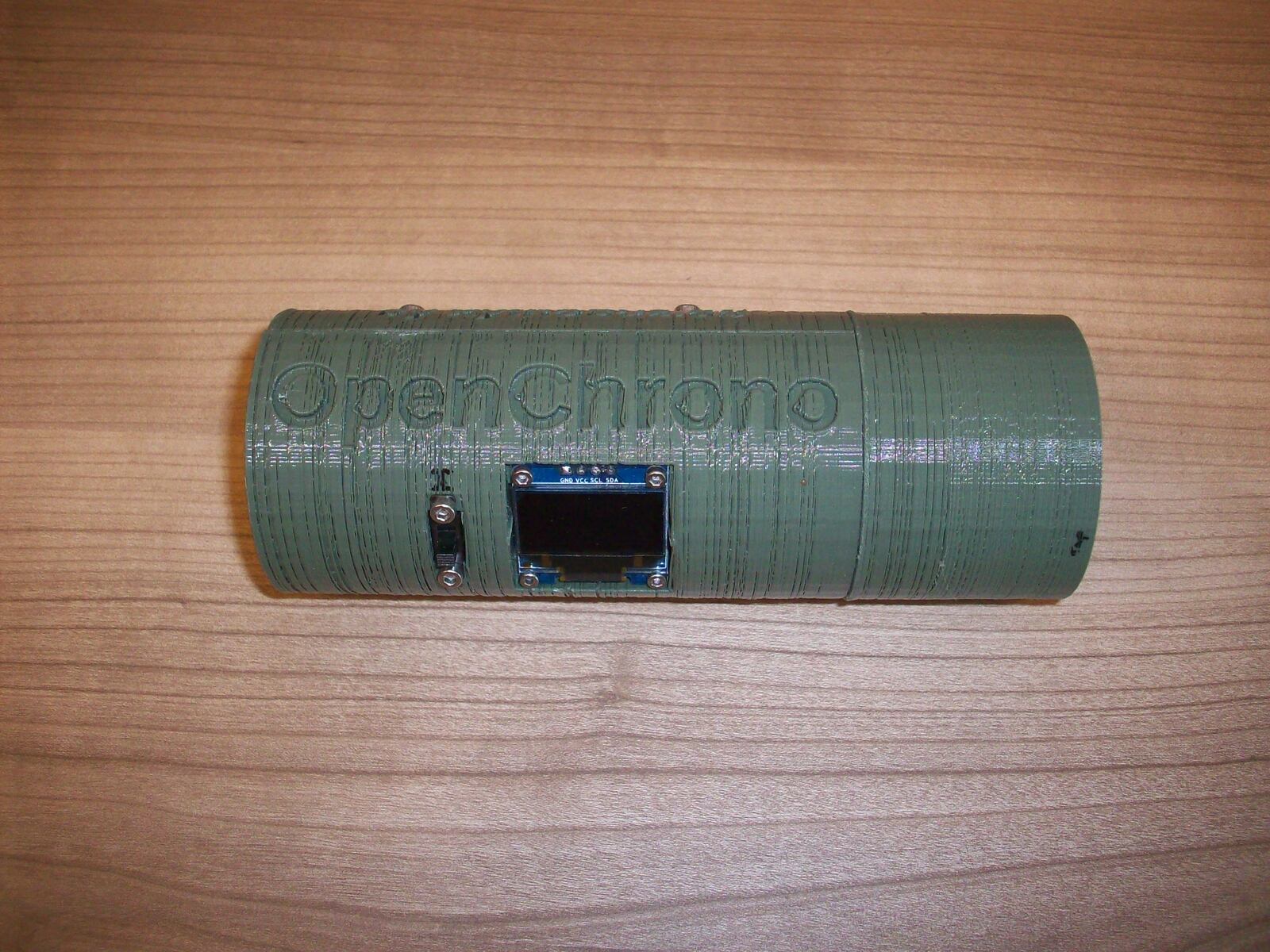
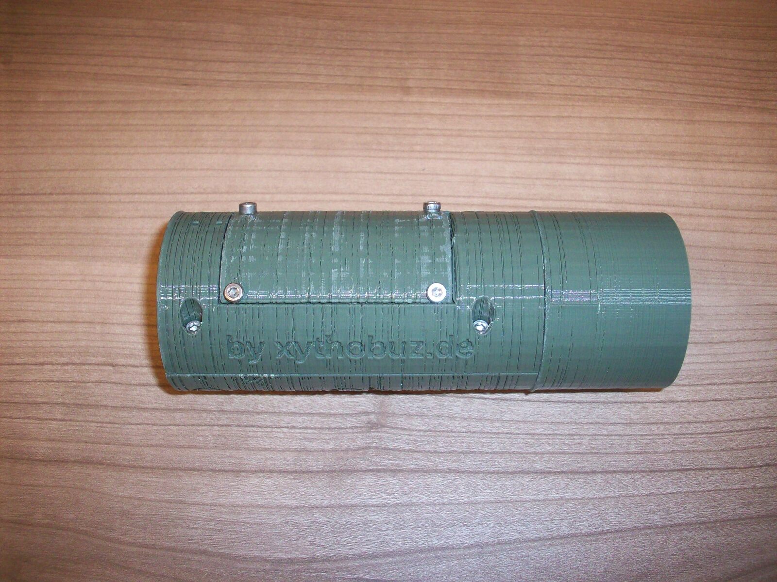
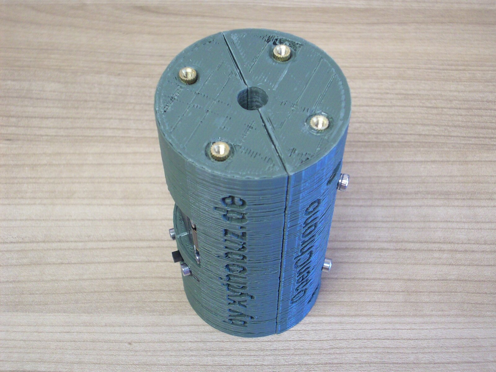
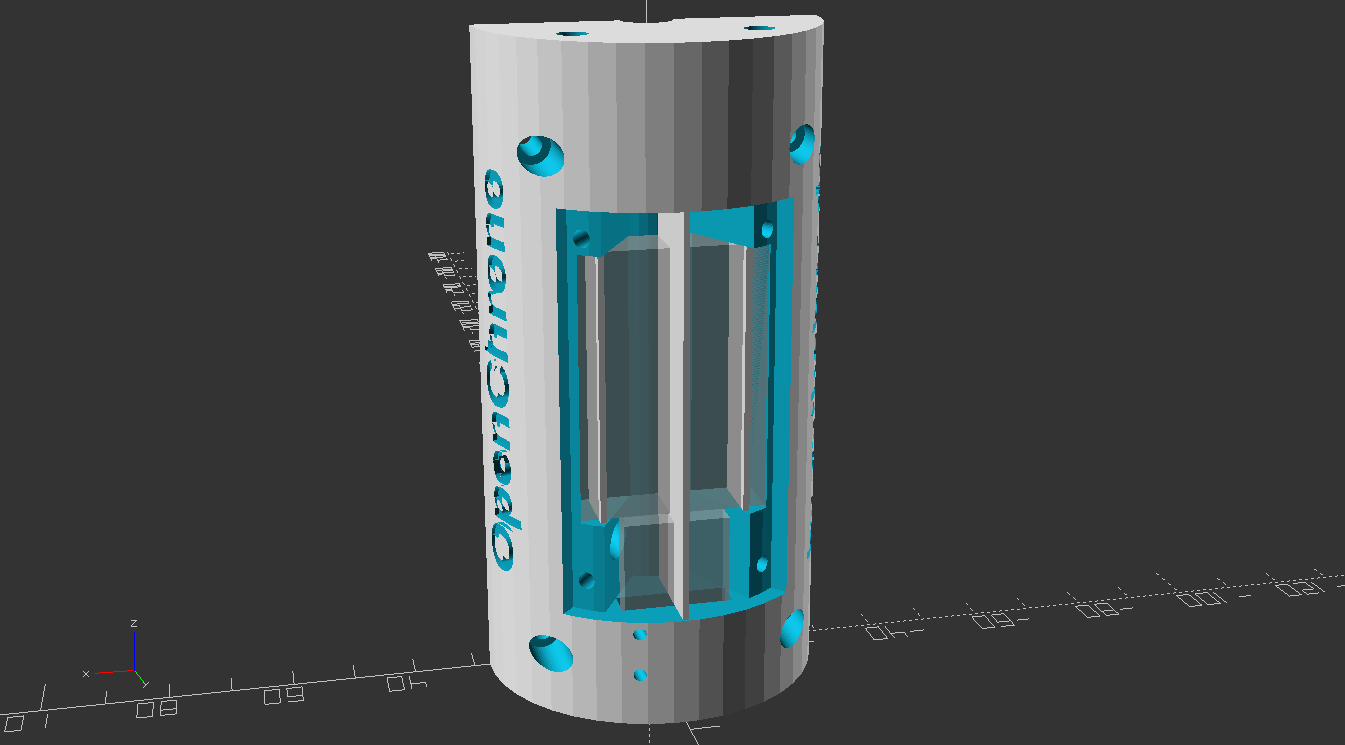
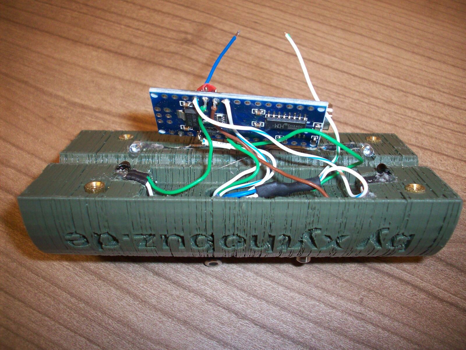
The housing for OpenChrono is 3D printed and was designed in OpenSCAD.
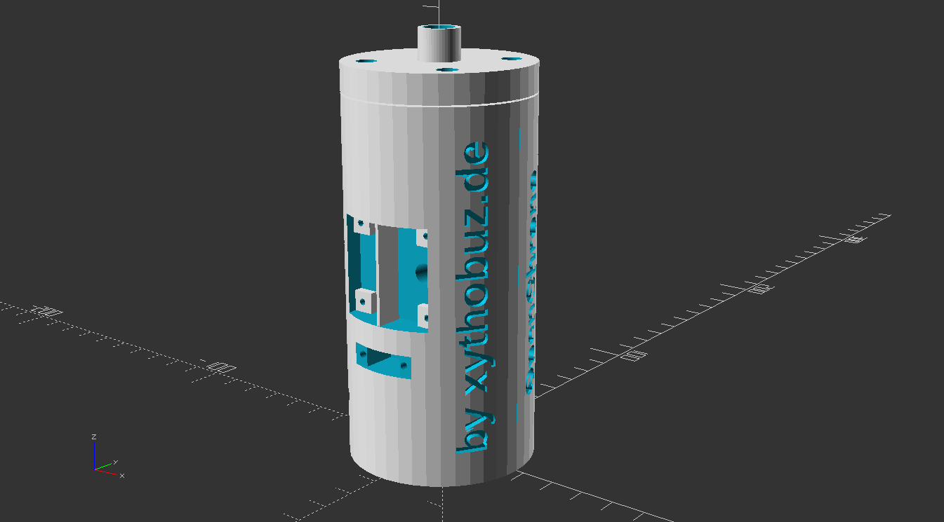
As usual the project is released as free and open-source software / hardware. You can find everything you need to build it yourself in the git repository!
Table Of Contents
- Prototype
- Mounting Options
- Test Results
- Build Guide
- Firmware
- Possible Future Improvements
- Potential Other Uses
- Links
- License
- More Pictures
Prototype
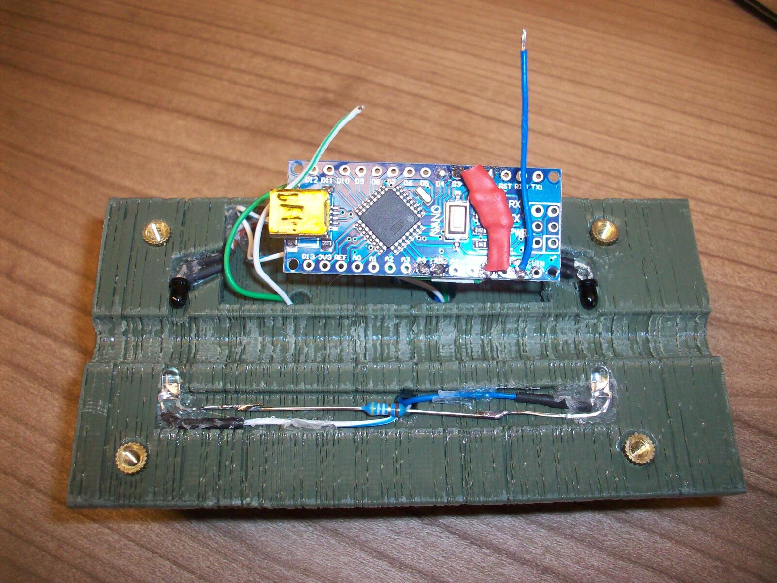
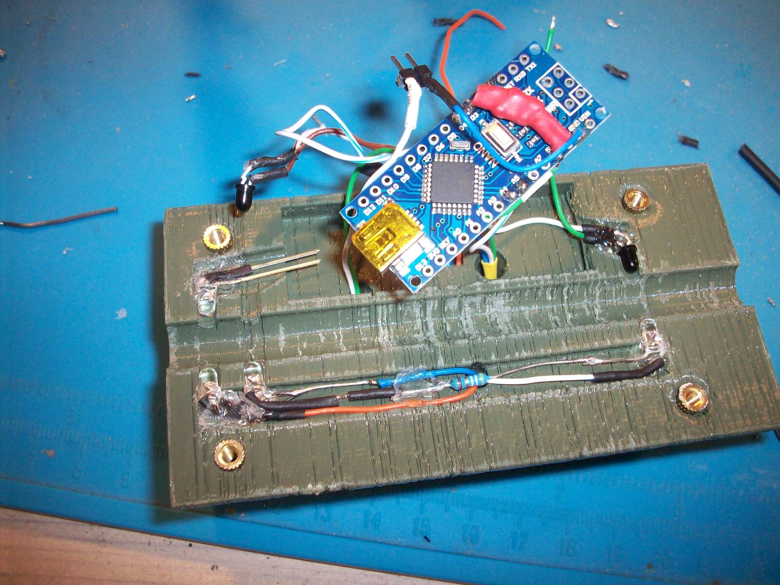
Because the optical sensing is dependent on environment conditions I decided to not do any breadboard prototyping and immediately went ahead and designed a case to test with. In this initial attempt I used an Arduino Nano, an SSD1306 128x64 OLED LCD and an AA-battery holder, all of which I still had left from other projects. For the IR phototransistor and LED I had to order some parts on eBay. This got me the SFH 309 FA-5 as well as some no-name 940nm IR LEDs.
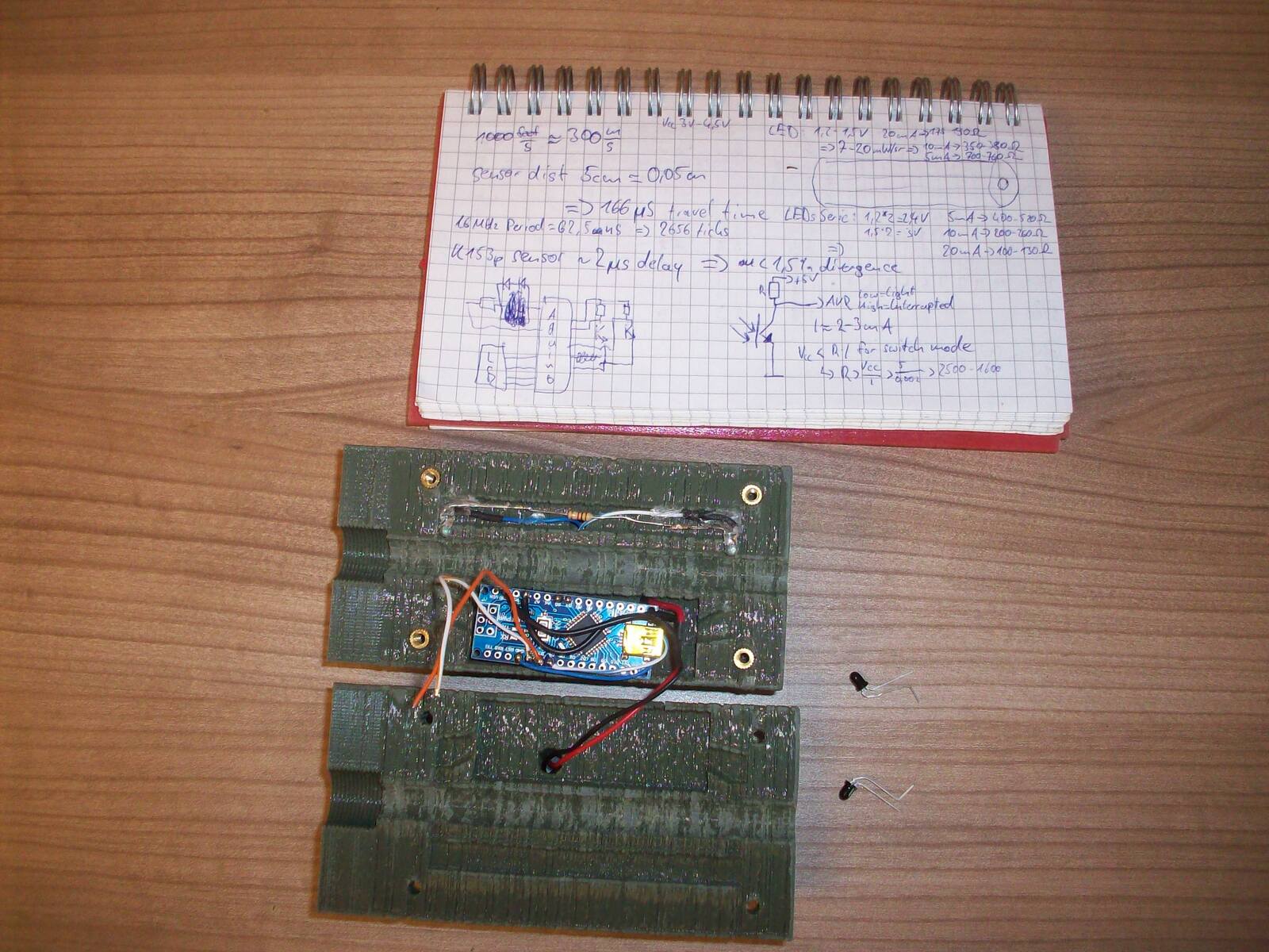
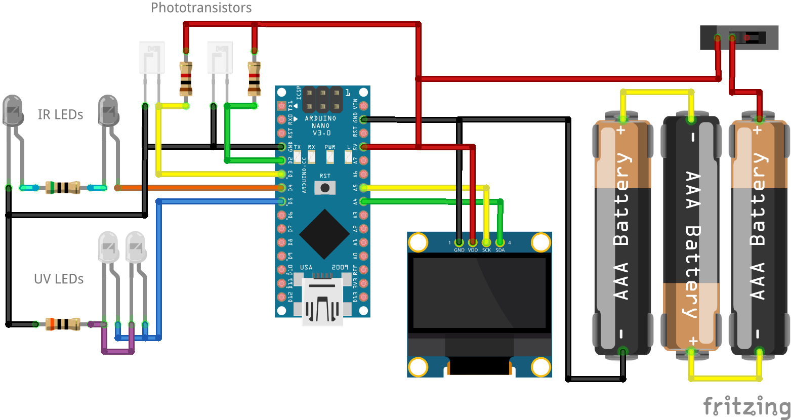
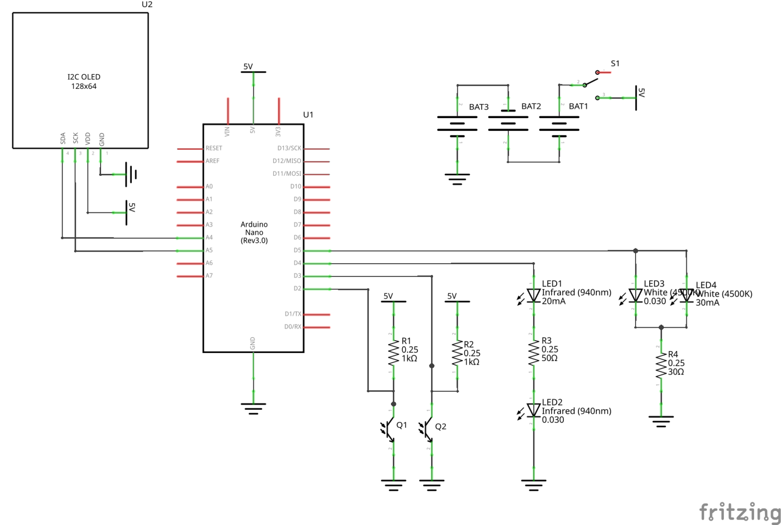
The circuit to connect the phototransistors to the Arduino is pretty simple. You can find details here. Signal processing with the Arduino is quick and easy when we have a binary signal available from the sensors, so the phototransistors are used in switch-mode. To achieve this, proper resistor values need to be selected. The current passed by the transistors is dependent on the amount of light hitting it, which is difficult for me to calculate, so I determined the proper values experimentally.
To do this I added external potis outside the case instead of resistors. You can also see a scope screenshot of both sensors triggering with a BB falling through the device.
The resistor value for the IR LEDs needs to be low enough that the transistors properly switch to a low-value when the light beam is uninterrupted. This was the case for me at around 50Ω to 100Ω, depending on the supply voltage. I think it makes sense to drive the LEDs at their current limit, so ~20mA.
Also the pull-up resistors for the transistors need their value to be low enough to quickly drive the signal to near supply voltage when the BB interrupts the light beam. A value of 1kΩ seems to work well there.
Mounting Options
Unfortunately the OpenChrono IR photo-sensing is a bit constrained in regards to the path of the BB. The sensors are only 3mm wide, and the BBs are 6mm wide commonly. So there can not be much deviation of the position of the BB in the light beam, otherwise the beam would not be fully interrupted and the speed measurement can not work. So we can not just add a big hole in the front of the unit which the user shoots through free-hand, like with standard commercial chronographs. We need to make sure the gun barrel is centered well in line with the sensor axis.
I already did some experiments in the past with 3D-printed silencer imitations for airsoft use. So printing matching threaded adapters was not completely new to me.
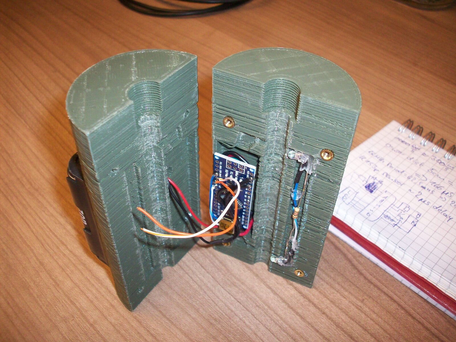
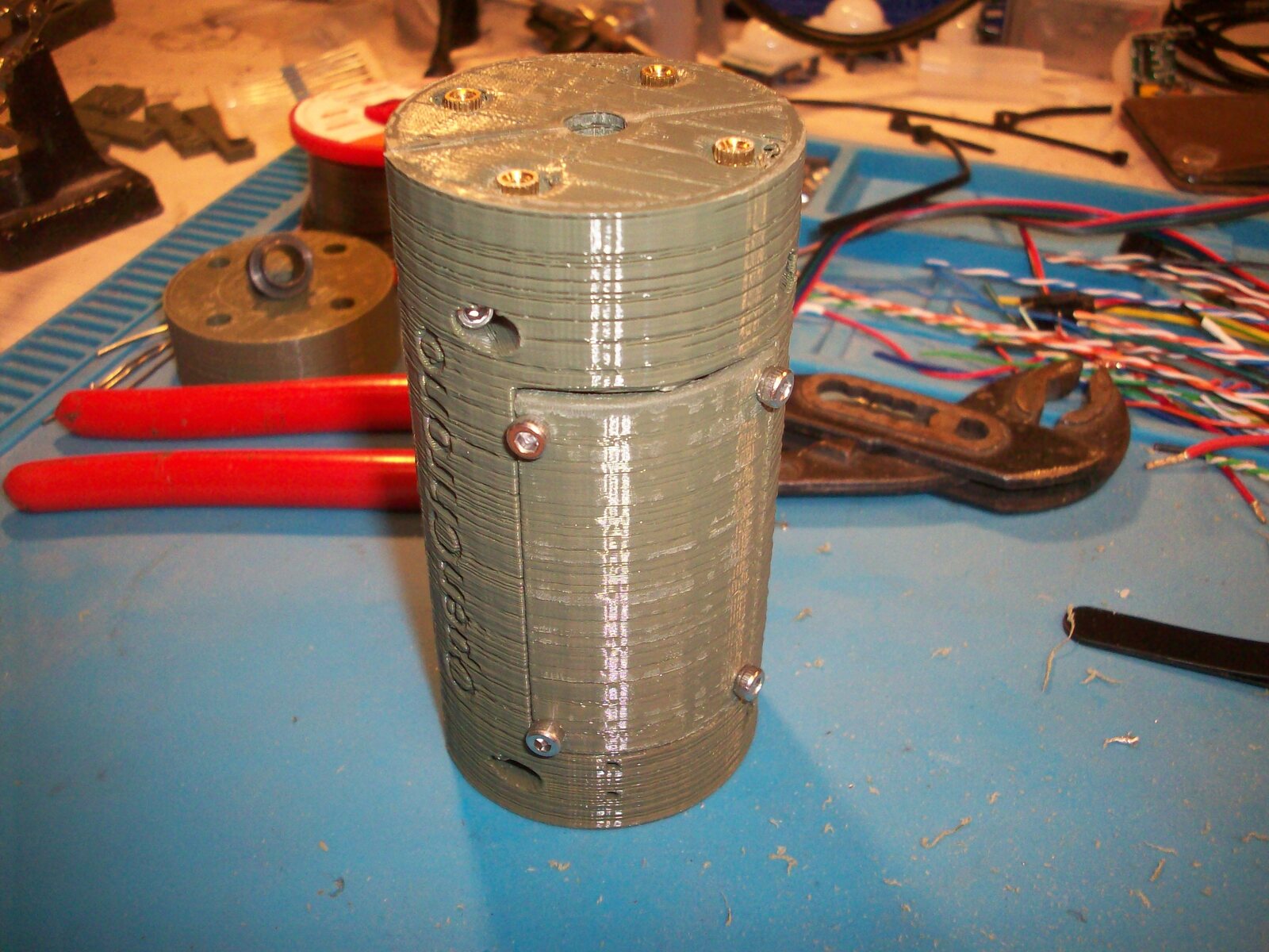
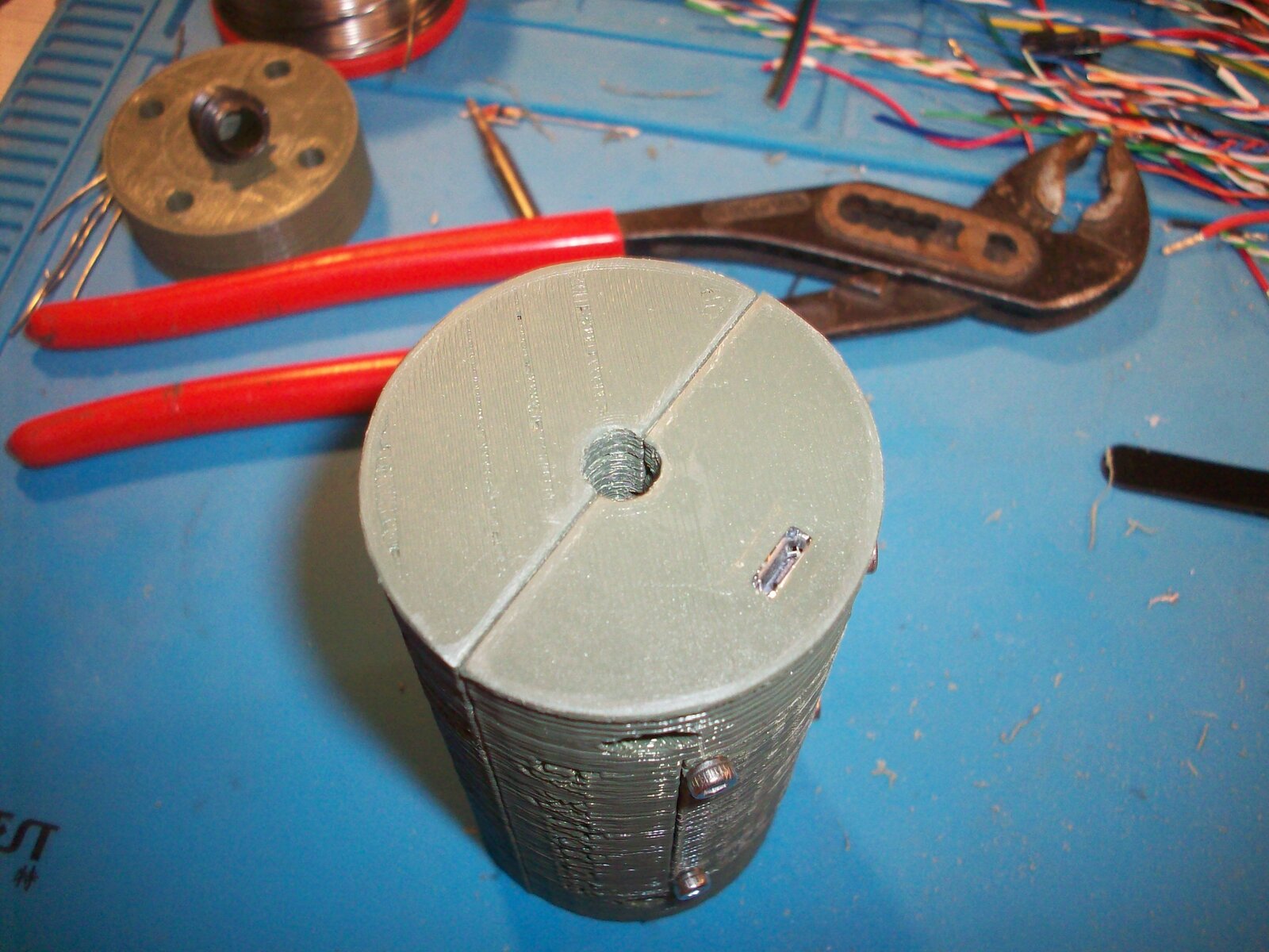
In my first prototype I printed a matching thread into the body of the device itself, split into two halves. This was not a great idea, when screwing both halves back together the threads did not align well enough to screw something in the top.
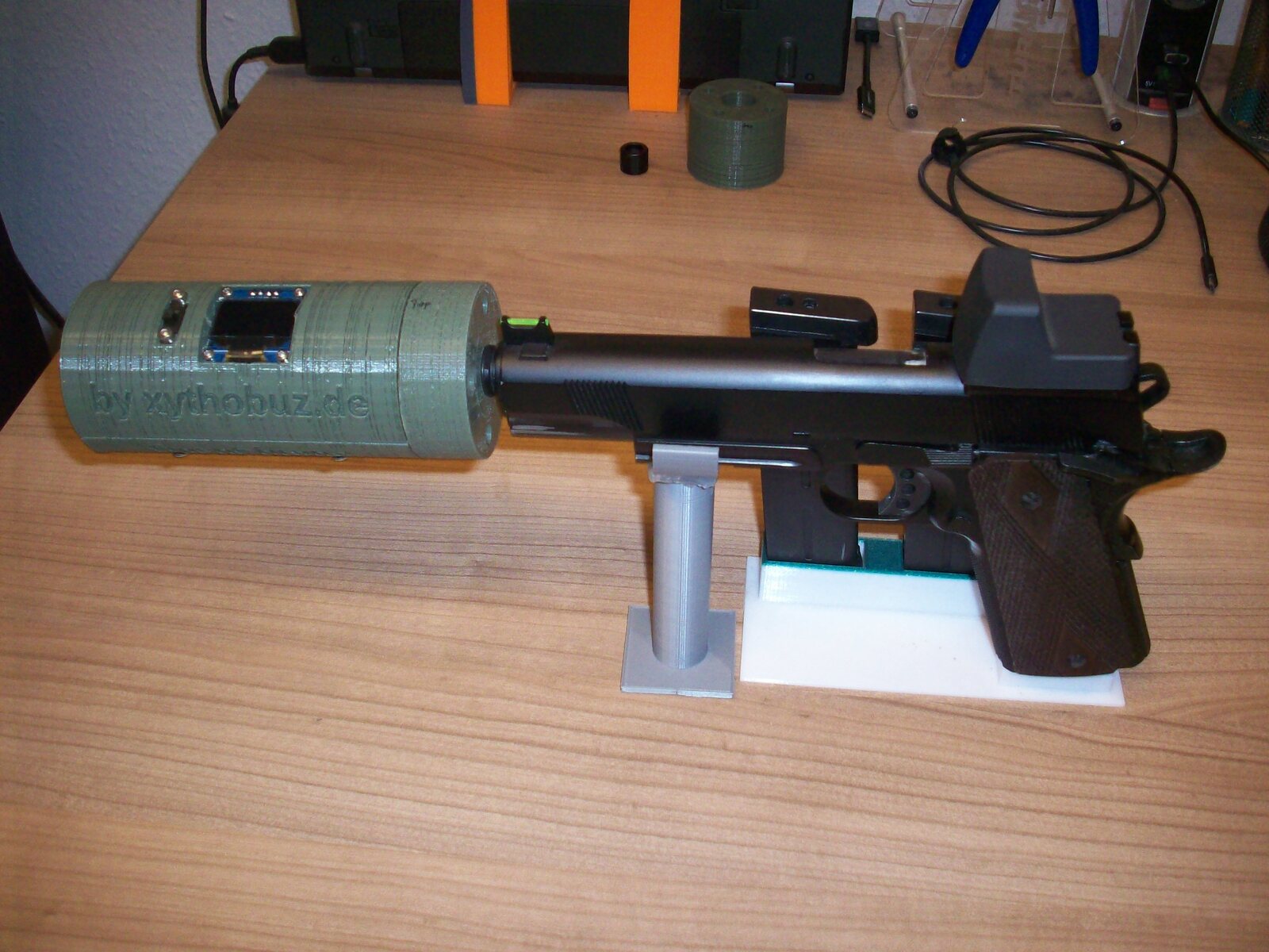
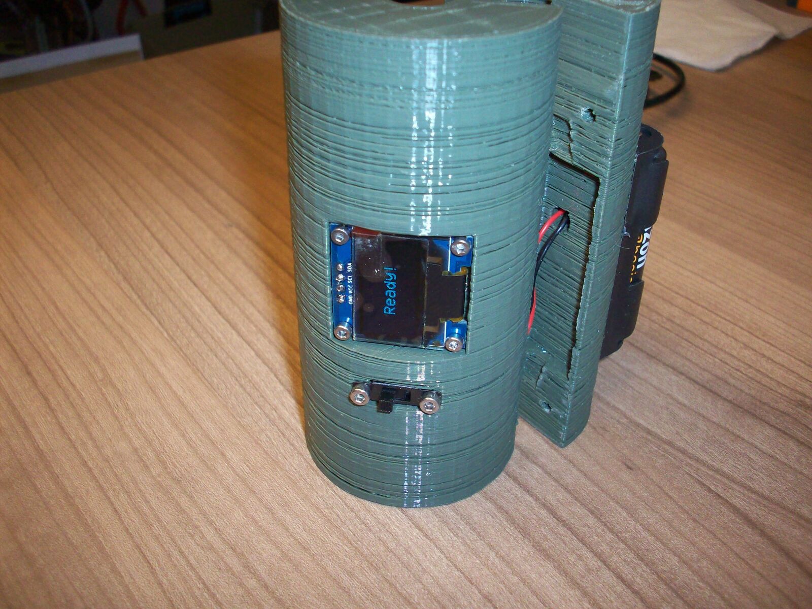
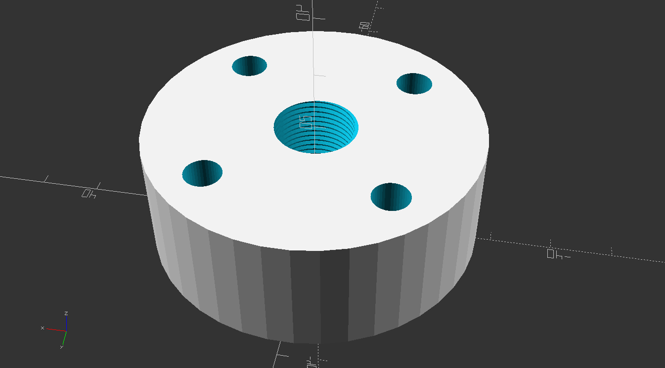
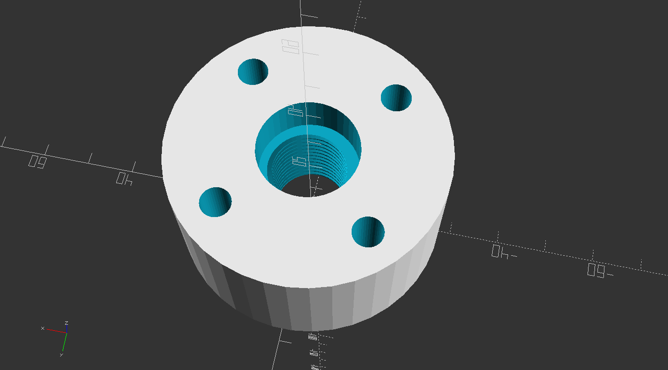
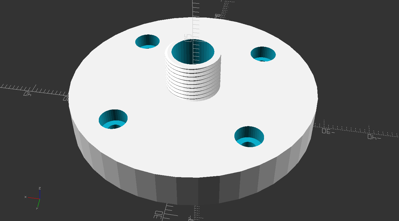
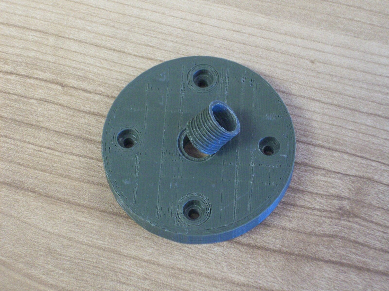
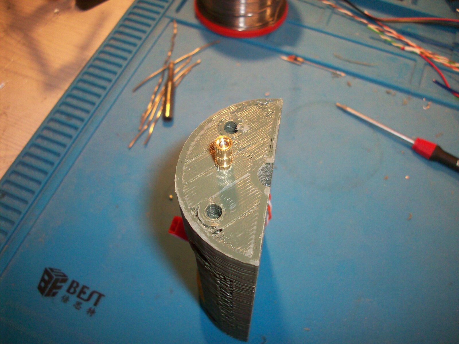
So I slightly re-designed it, making the threaded adapter plate a separate part that screws onto the body of the device. In this way it can also more easily be fitted to different guns. For my M11 I had to also add an extension plate because it has some length of barrel sticking out past the threaded part.
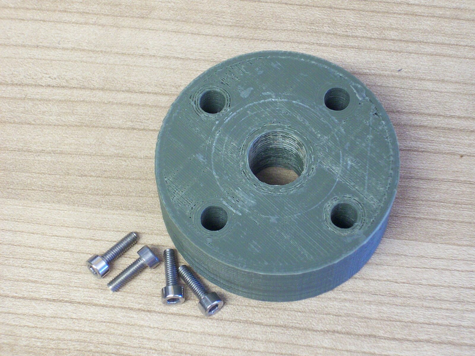
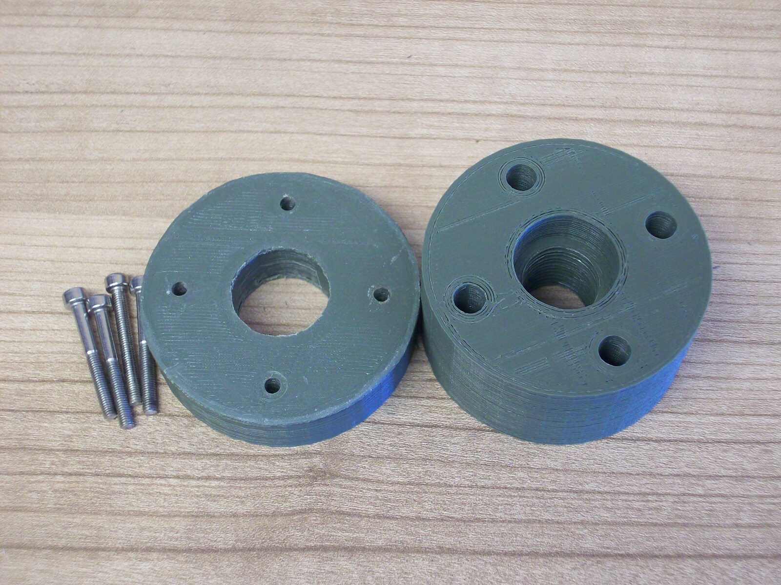
The 3D models are made using the OpenSCAD threads library by Dan Kirshner.
Test Results
Attaching the whole unit to a airsoft gun barrel turned out to be a bit tricky.
M1911 Red-Gas Blowback (Part 1)
The first gun I wanted to test with is a full-metal TM 1911 clone with a gas blowback system. The repetition imparts a big impulse on any barrel attachment, big enough to break my self-made silencer adapters in the past after a single-digit number of shots. Of course OpenChrono is much heavier than a plastic silencer imitation, so predictably it broke after only three test shots, even though I supported the weight with my hand. Additionally the impulse in combination with the inertia of the AA batteries caused the supply voltage to cut out in the moment of shooting. So no usable measurements could be obtained.
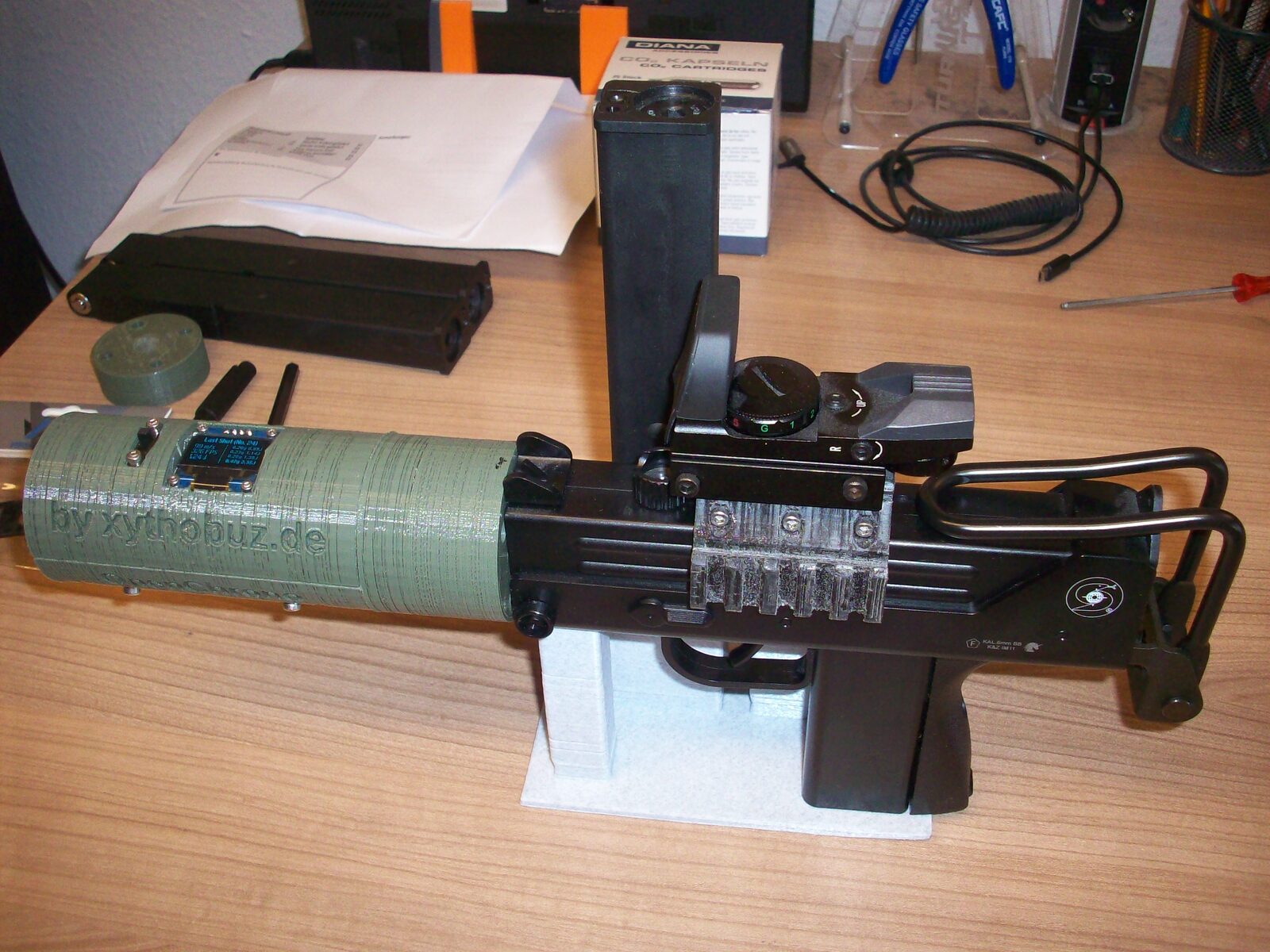
M11 Co2 Non-Blowback
For the second test run I tried to use a non-blowback ASG Ingram M11 Co2 gun. Besides some unrelated problems with the magazines it worked relatively well. Even without blowback the impulse on firing is still big enough to cut out the AA battery power. But this time it was easily possible to hold the batteries in place by hand while shooting, avoiding the problem. The measurement results looked mostly realistic, ranging from nearly zero with an empty gas capsule, up to ~1.5J with a full one, which roughly matches the specs of the gun (which hopefully was to be expected, as it is completely unmodified). With one magazine I got some faulty readings, counting a single shot multiple times with ridiculously high velocities. I suspect this was caused by oil droplets from a maintenance capsule that was in the magazine previously. But because of the aforementioned magazine problems I was only able to shoot about 20 BBs for this test.
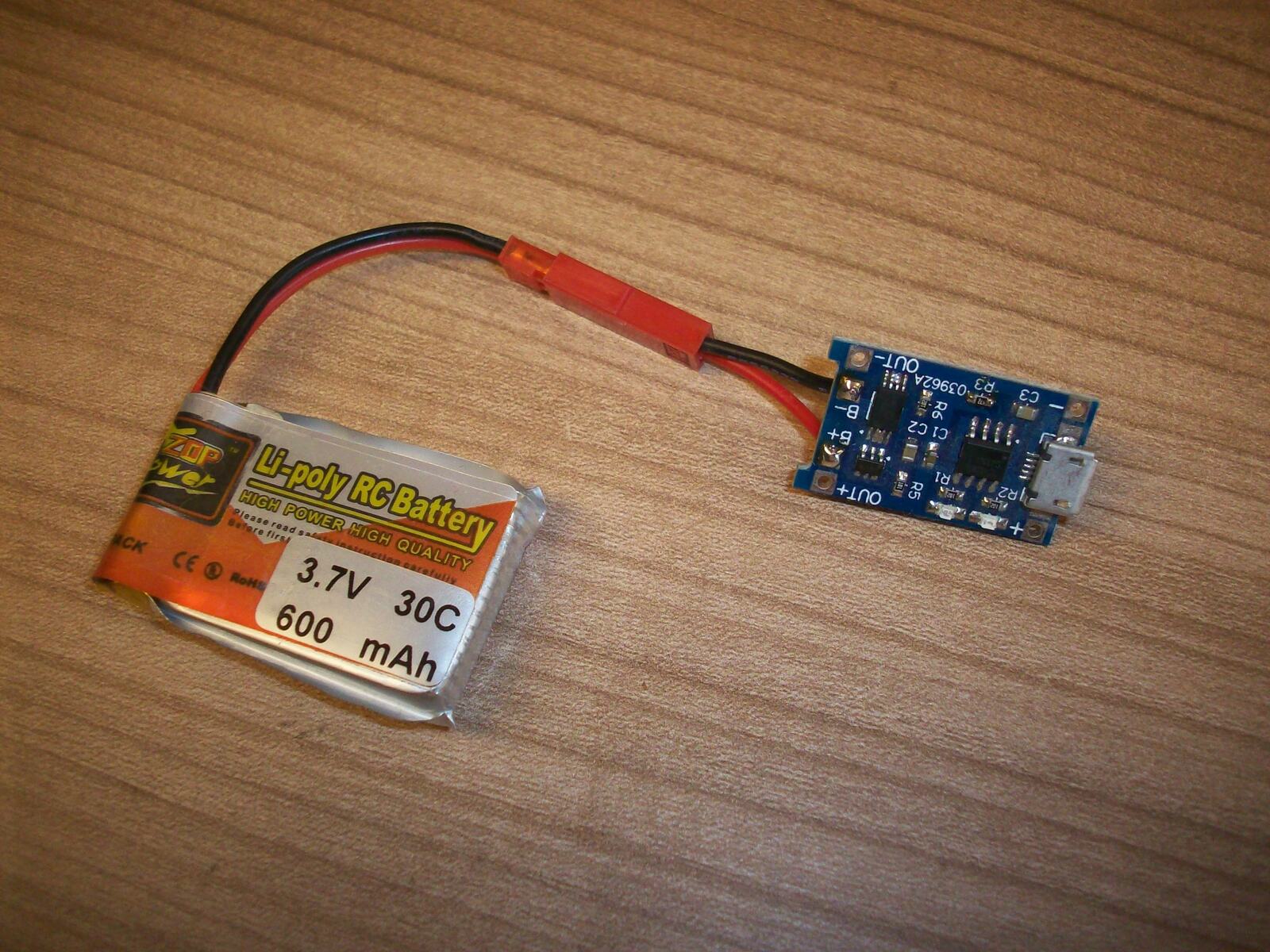
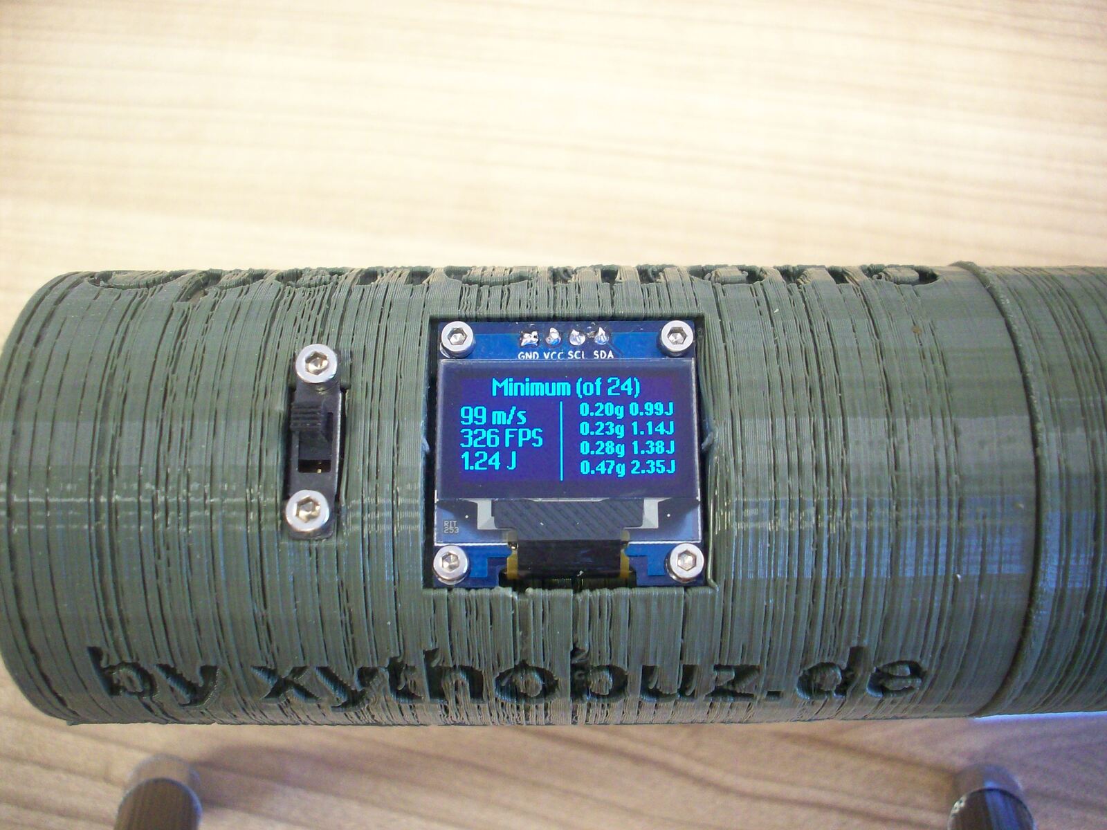
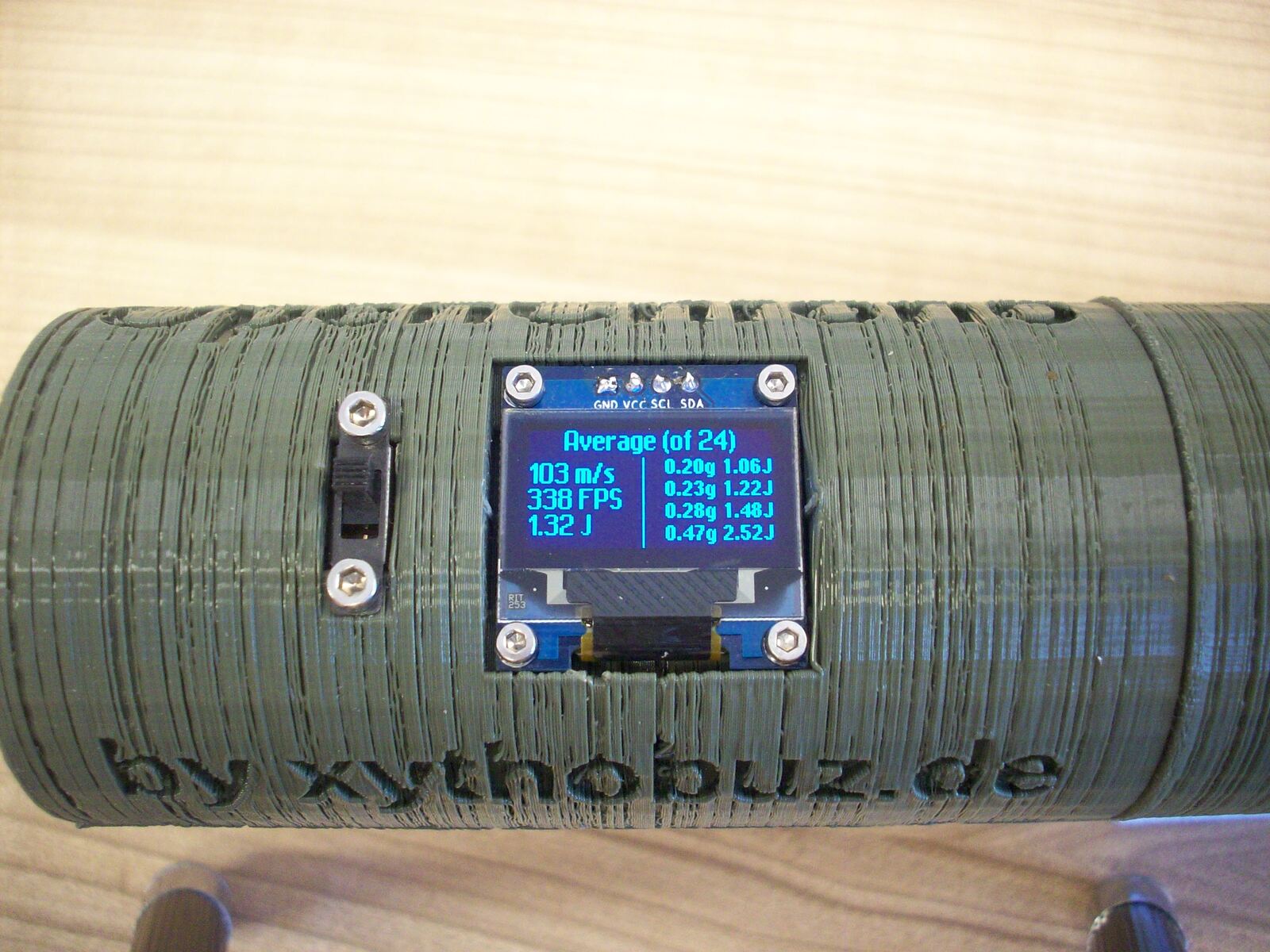
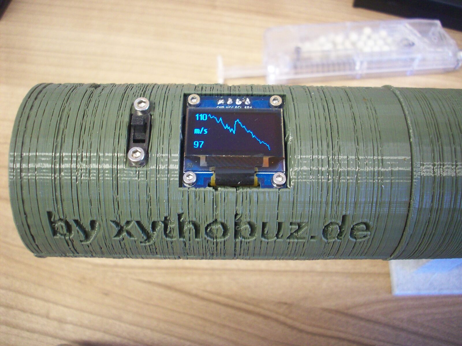
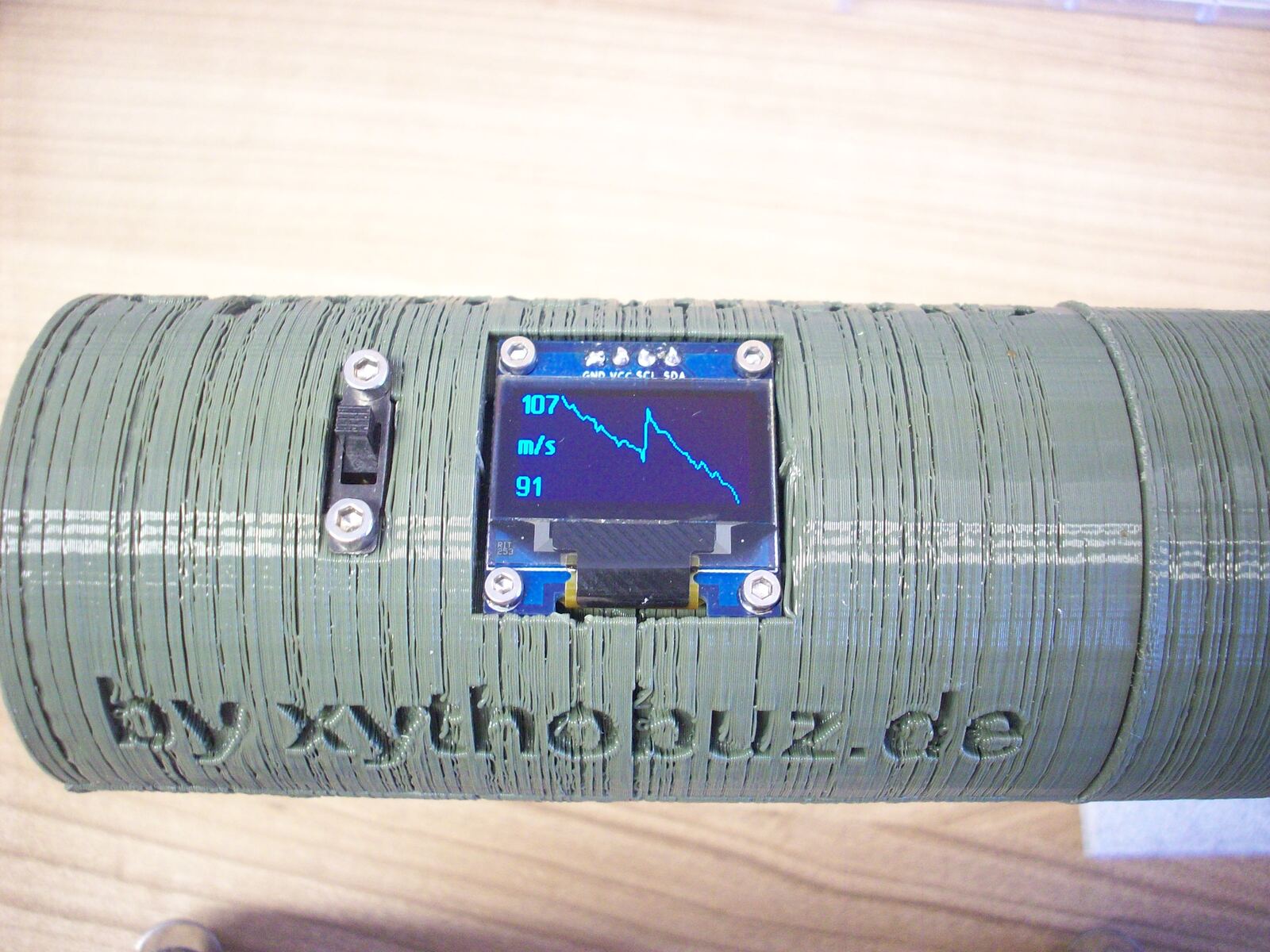
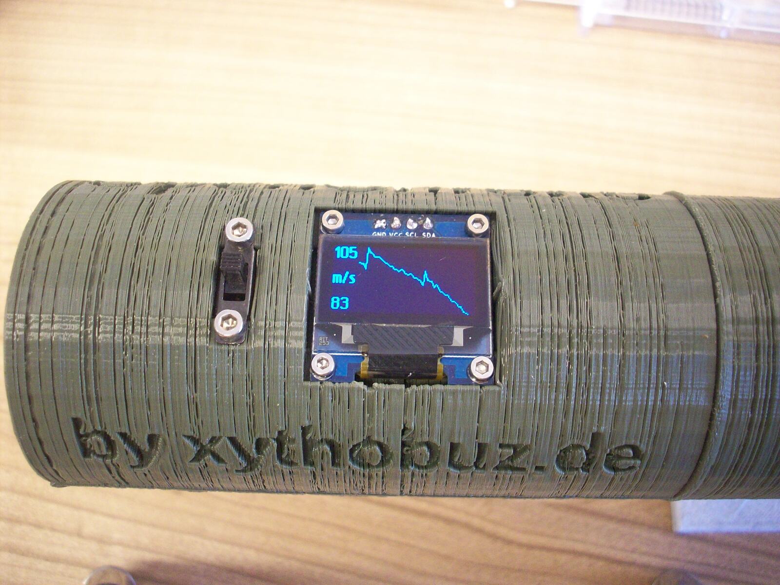
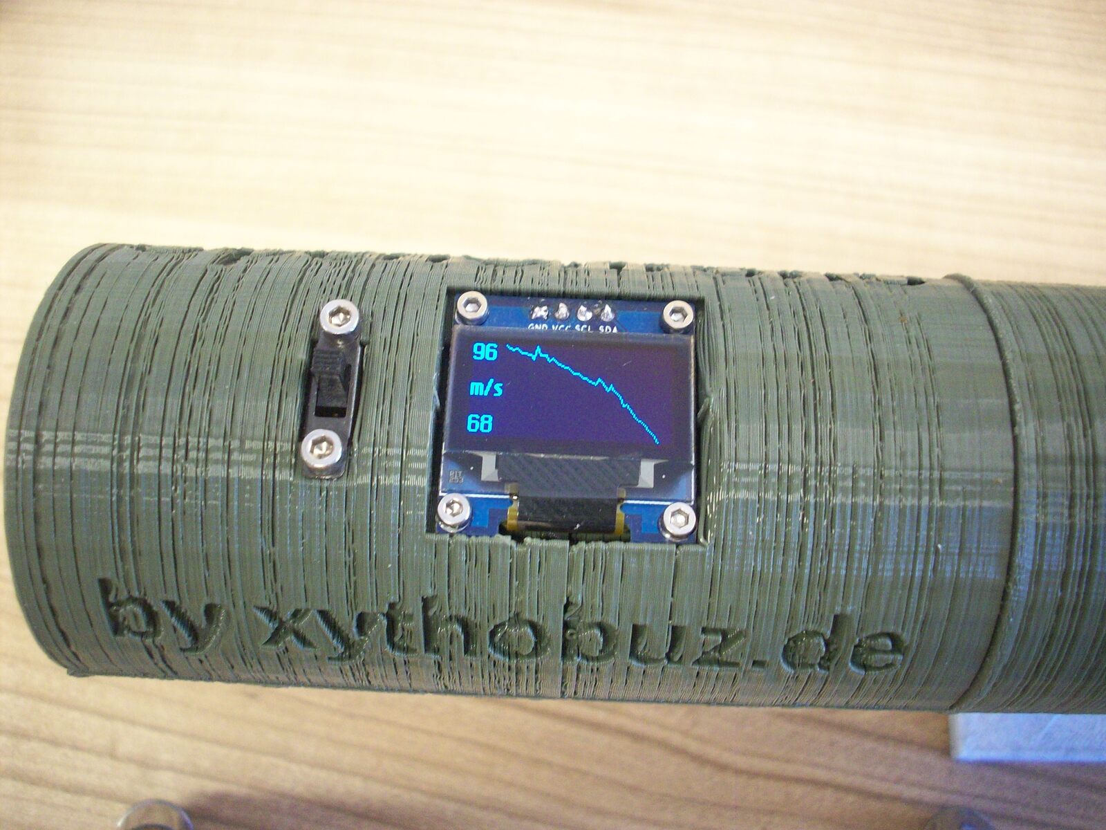
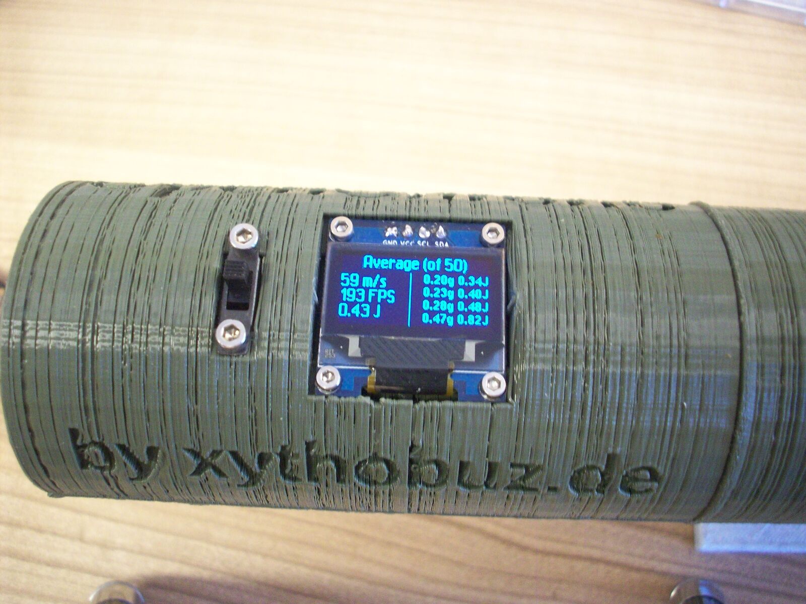
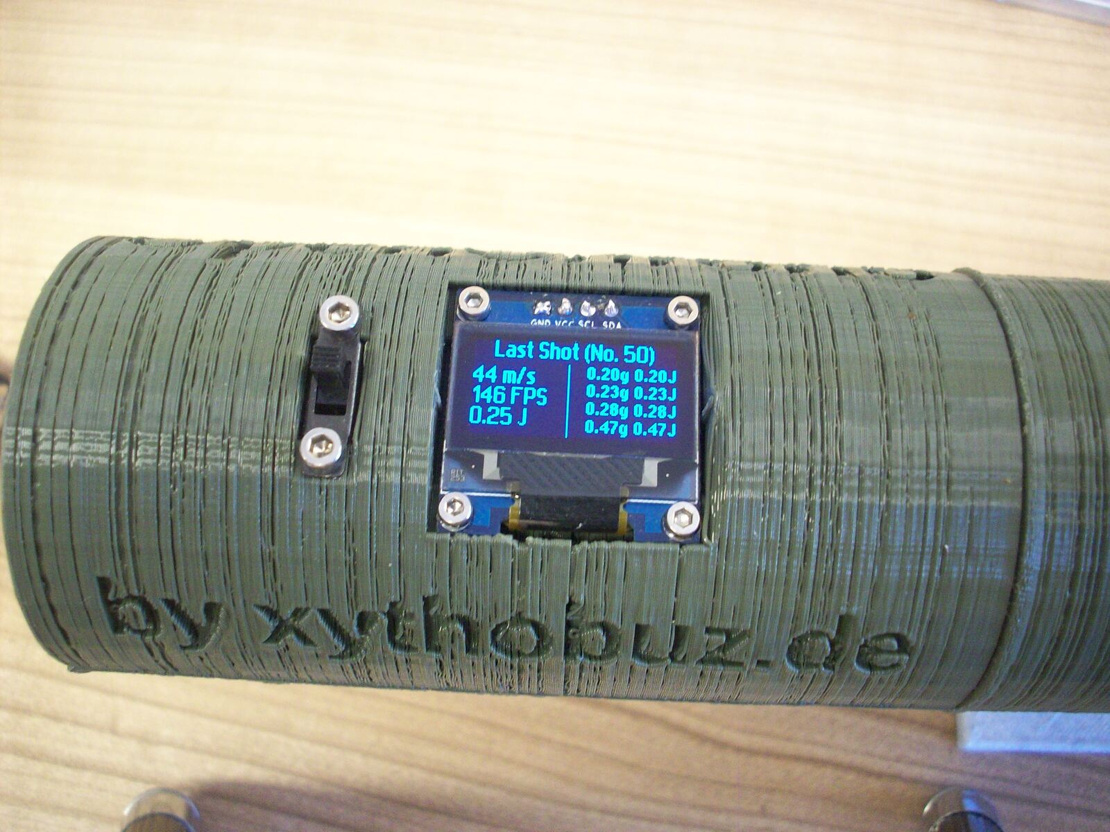
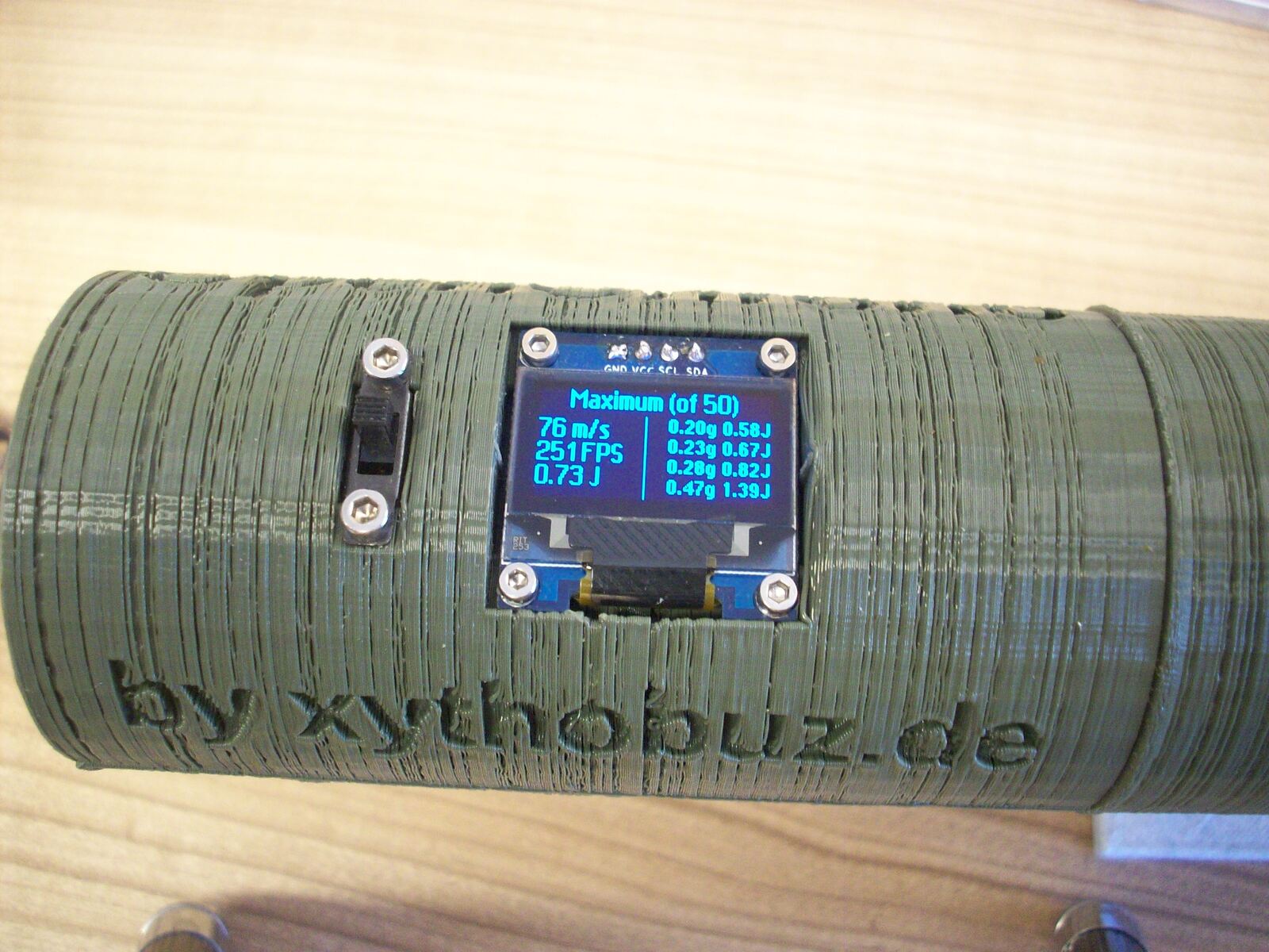
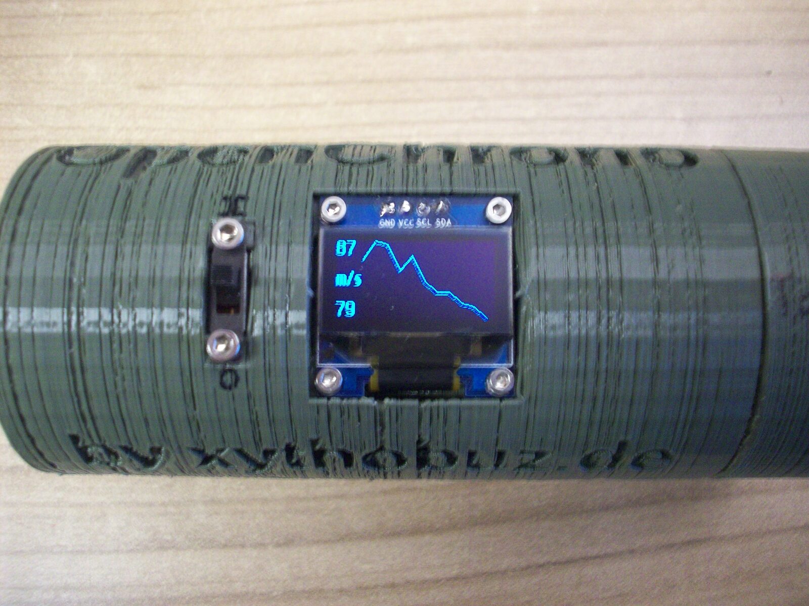
To be able to properly measure anything I next redesigned the hardware to use a soldered-in LiPo battery that won't disconnect on firing. For the next test with the M11 I went through about 200 shots or more without seeing a single false measurement.
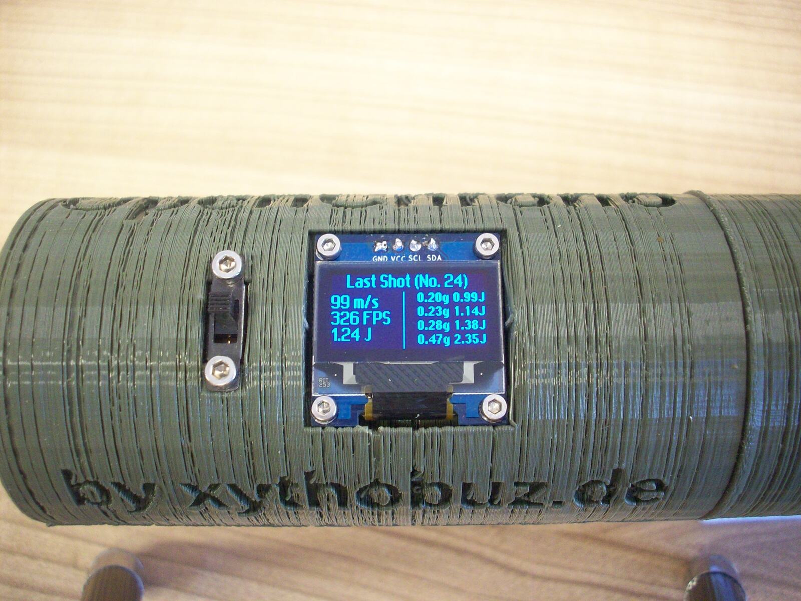
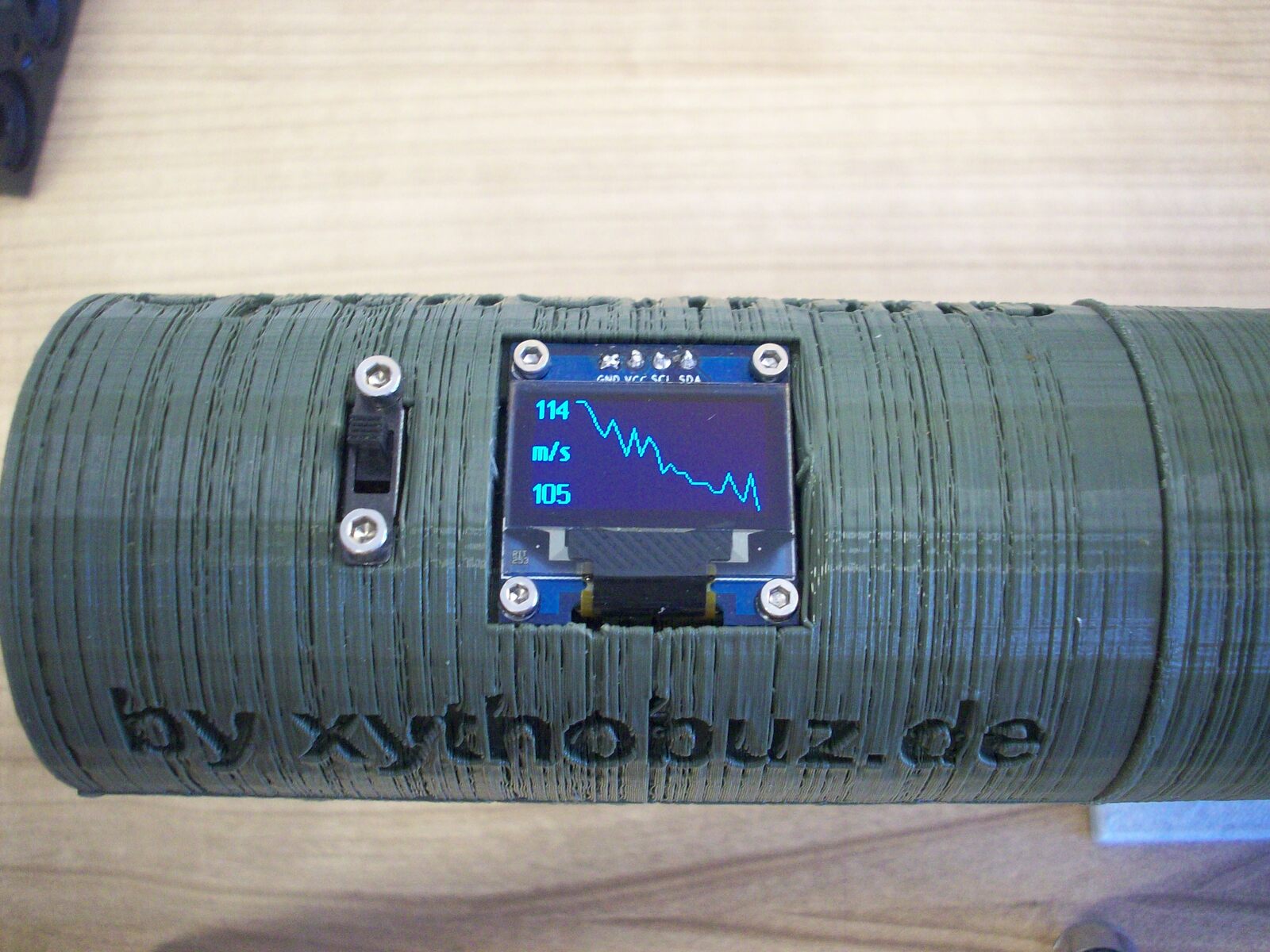
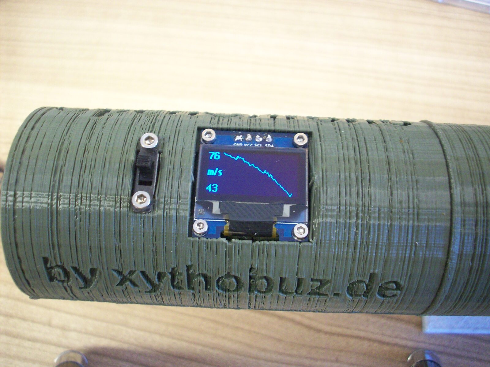
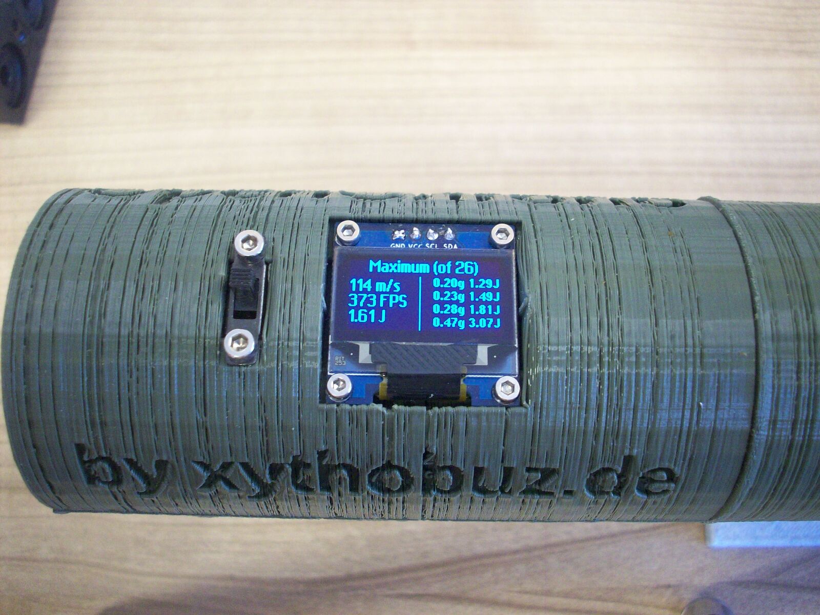
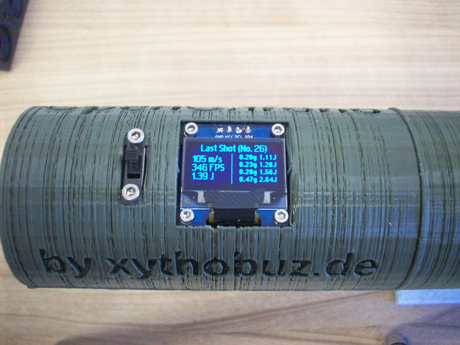
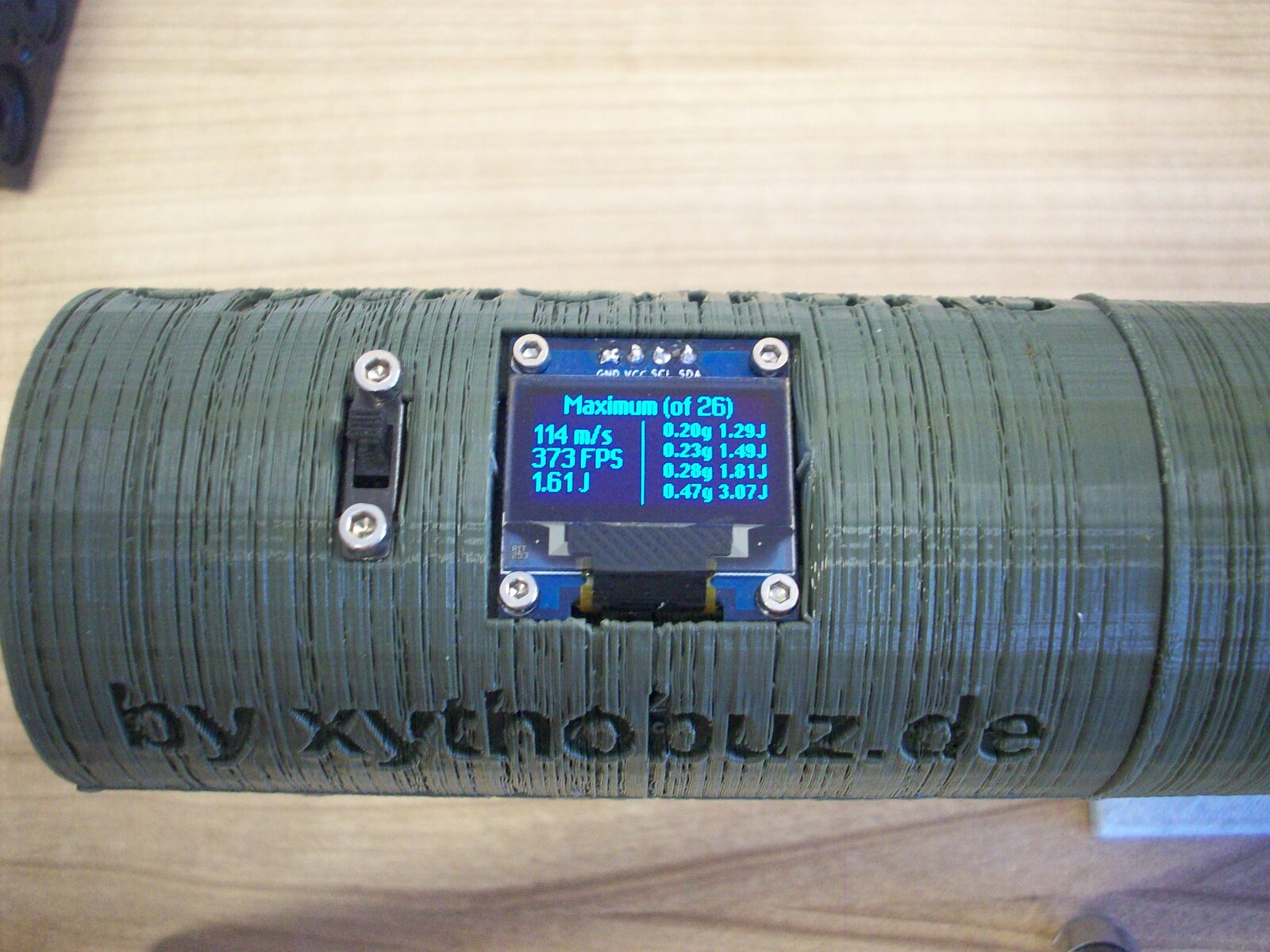
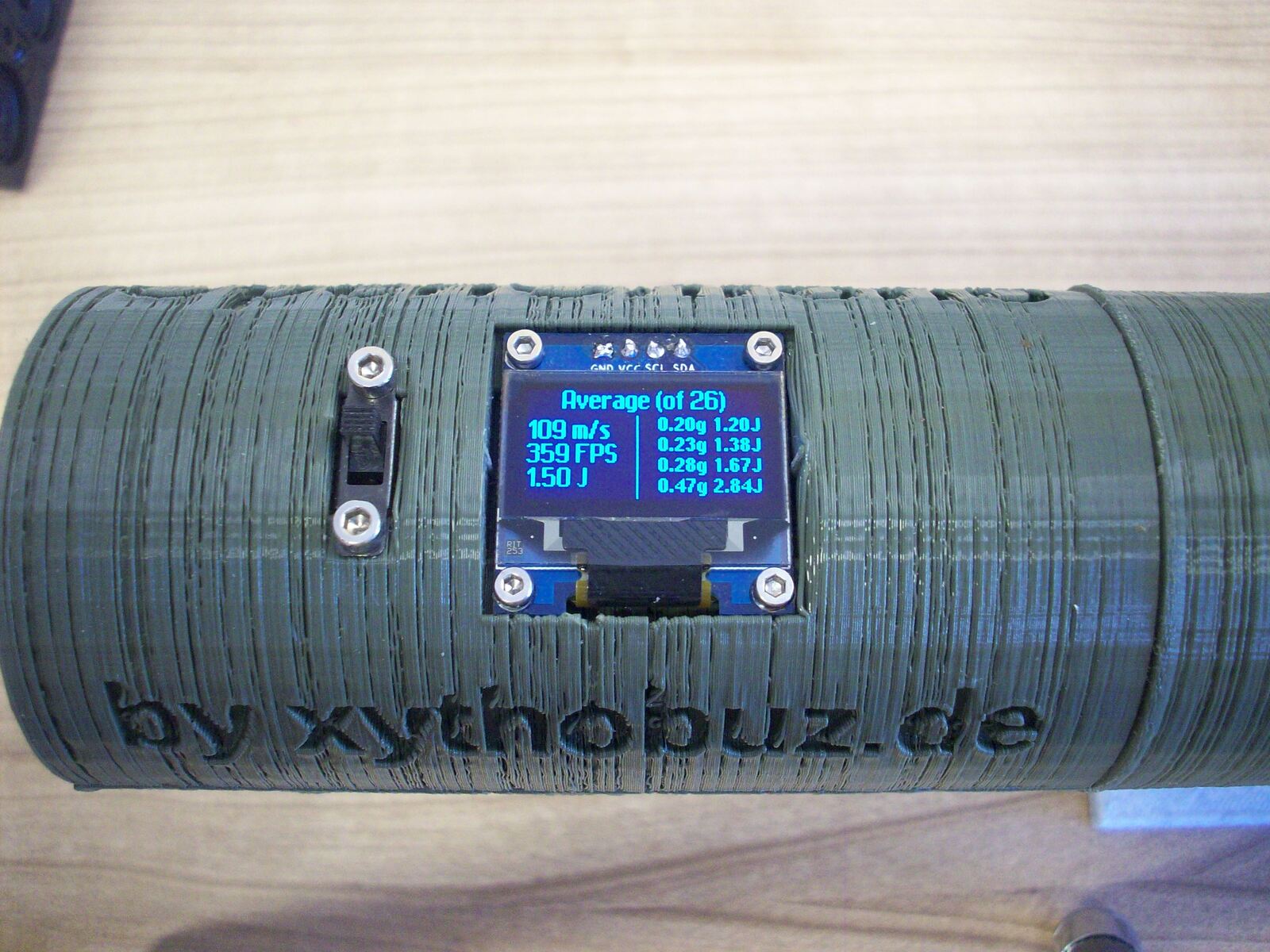
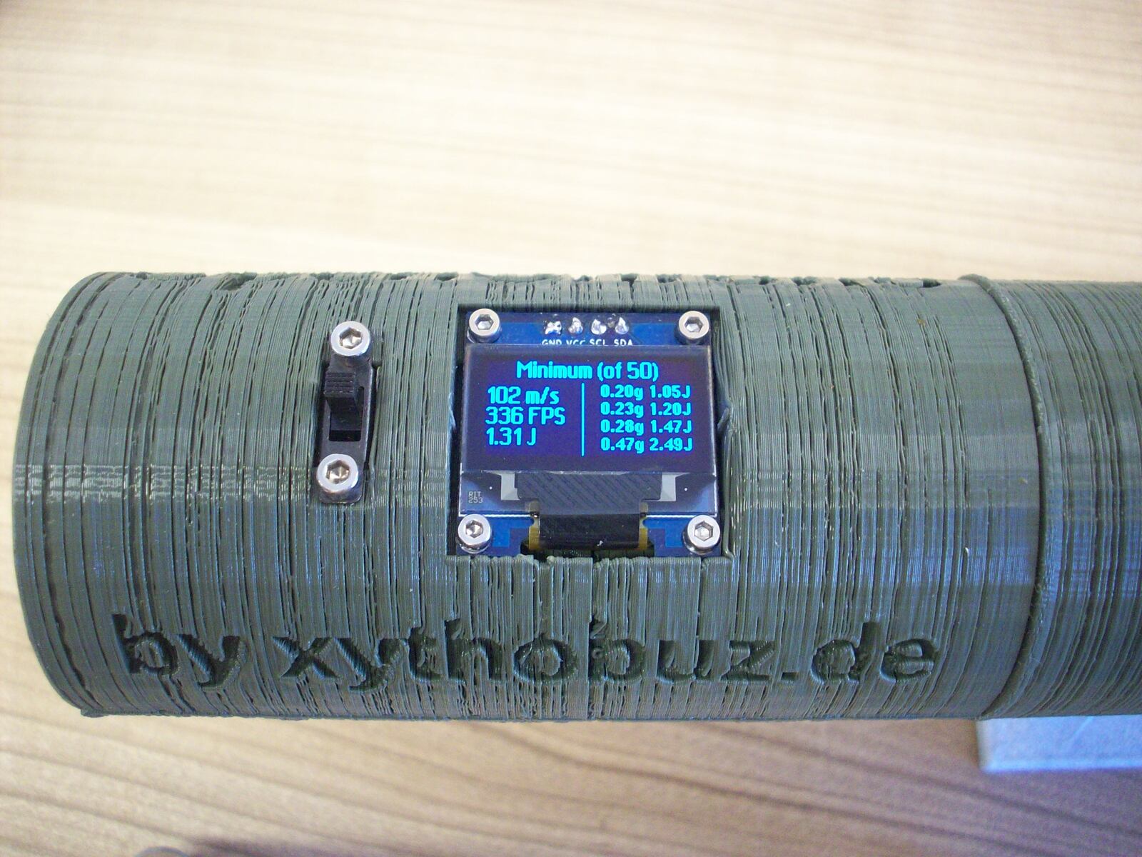
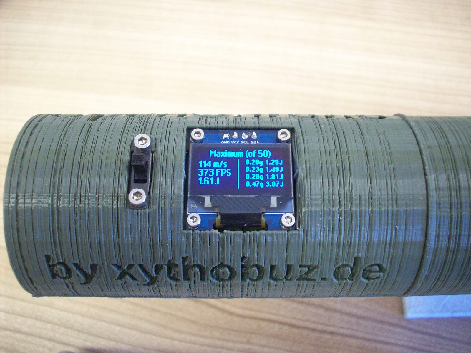
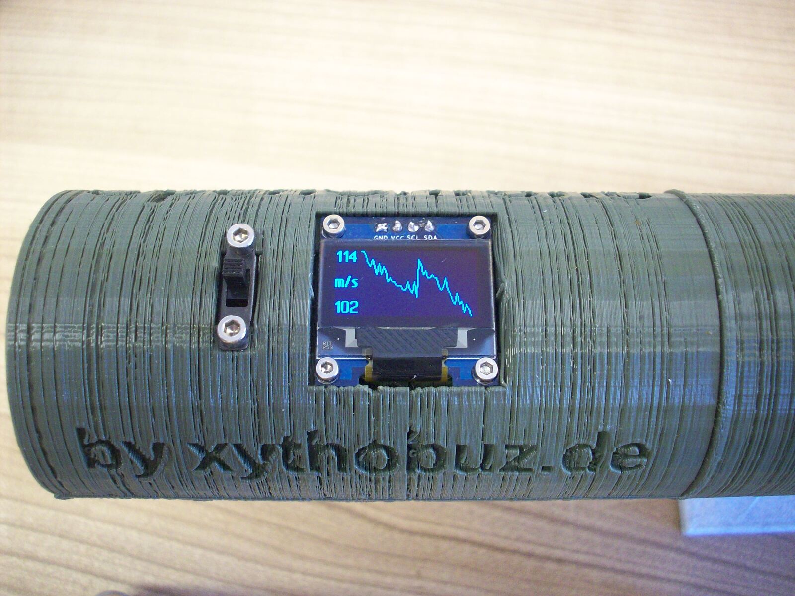
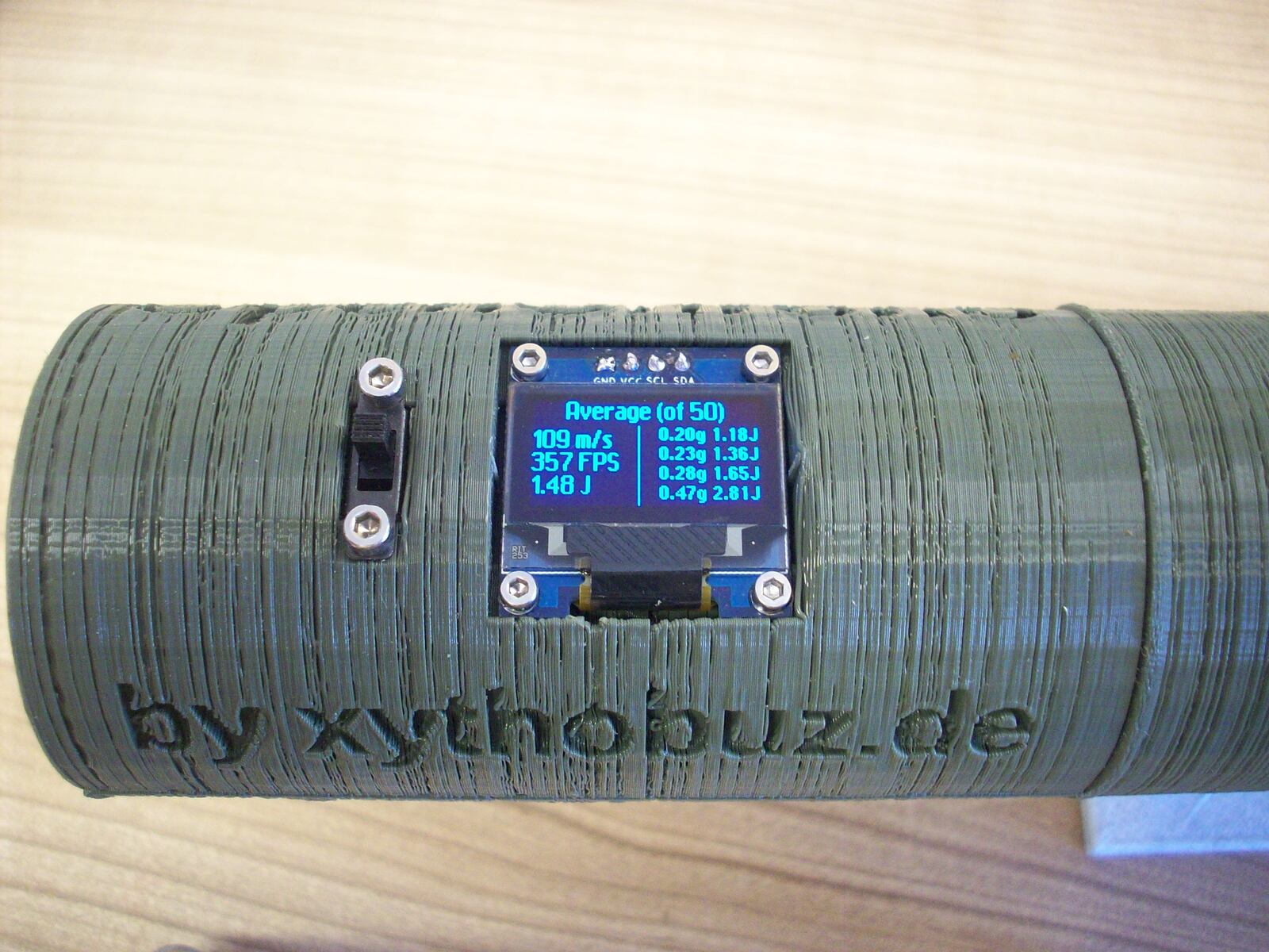
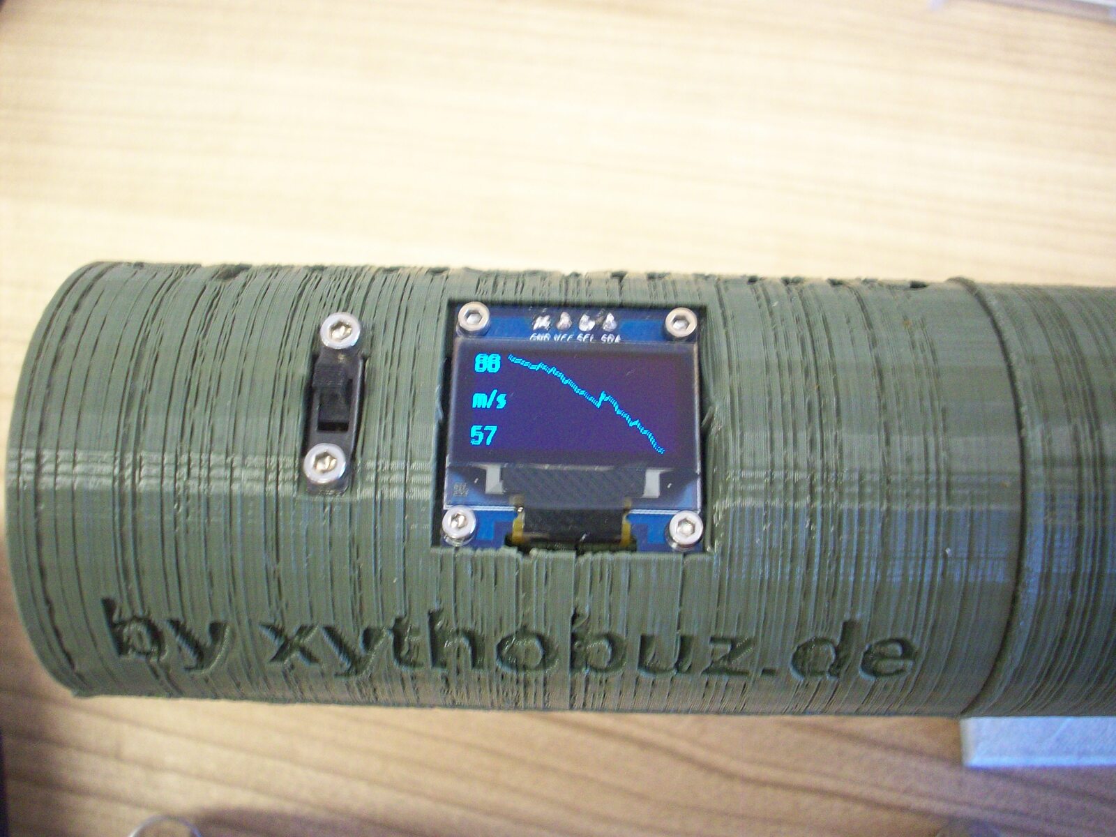
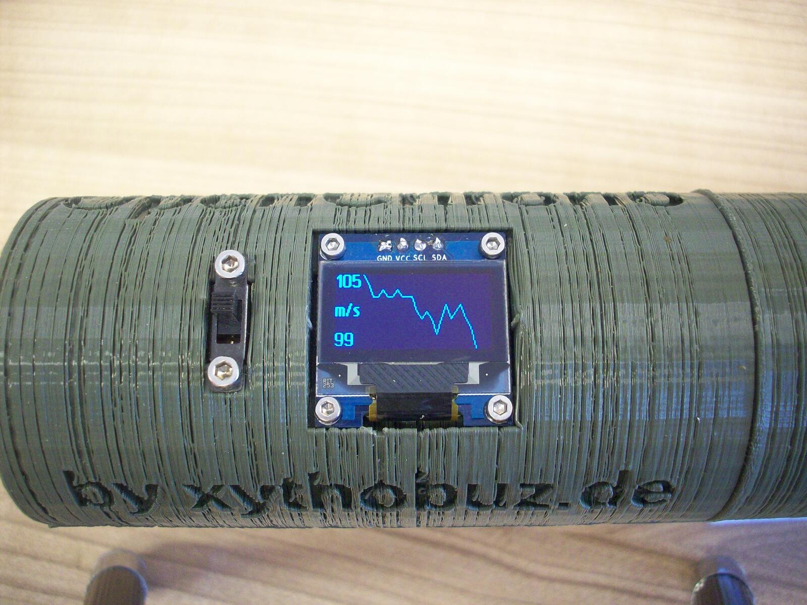
The results are interesting, you can see the behaviour of the Co2 capsule well. With the first shots with a fresh capsule the speed is about 105m/s, which is 1.39J at 0.25g BB weight. The speed then reduces with each shot and goes back up again when waiting long enough between shots, as the capsule slowly heats up again. With the last couple of shots I took only 0.23J were left.
M1911 Red-Gas Blowback (Part 2)
After getting a metal threaded adapter from 14x1mm-CCW to 12x1mm-CW I was also able to continue testing with my 1911 blowback pistol. It worked fine! The printed female thread can withstand the forces much better.
The measured speed / energy seems a bit low. I suspect that's because I was using a propane magazine with a Co2 slide spring. Another topic is the weight of the OpenChrono device. When attaching large weights to the front of a 1911-style mechanism, the force required to actuate the slide is much larger. Therefore the valve is open for a longer time, increasing the gas usage. So the magazine gas chamber empties quickly and, I suspect, the BB force is reduced as well. That's a drawback of this style of chronograph mounting for some guns.
Tracer Unit
Unfortunately the tests with the UV LED tracer did not work out that well.
When dropping a BB through the device it actually visibly lights up as expected.
But the velocity is far lower in this case compared to a real shot.
When trying the same with either of my two guns the BB is not visible at all, even in complete darkness.
The power output of the two LEDs is simply not enough (2 × 3V × 20mA = 120mW).
Experiments done by airsofttech.dk suggest we need at least 20 times as much power, with ~3W going into the LEDs.
So for now I do not recommend to build OpenChrono with the tracer option as it currently can be found in the repository.
Build Guide
Also take a look at the "Hardware" section of the README.md. You can find detailed parts lists, schematic and wiring plan there as well.
Parts
Before starting the build you need to acquire the following parts.
| Description | Type | Count | Link |
|---|---|---|---|
| Arduino Nano | 1x | Arduino Store, AliExpress | |
| LCD 128x64 I2C | SSD1306 0.96" | 1x | AliExpress, eBay.de |
| Slide Switch | 1x | AliExpress, eBay.de | |
| IR Phototransistor | SFH 309 FA-5 | 2x | Reichelt, eBay.de |
| IR LED 3mm | 940nm | 2x | AliExpress, eBay.de |
| LiPo Battery | 600mAh | 1x | AliExpress, eBay.de |
| Charging Module | TP4056 | 1x | AliExpress, eBay.de |
| Resistor SMD | 4kΩ, 0603 | 1x | eBay.de |
| Resistor | 1kΩ | 2x | eBay.de |
| Resistor | 50Ω | 1x | eBay.de |
| Screws (Display) | M2 10mm | 4x | eBay.de |
| Screws (Switch) | M2.5 10mm | 2x | eBay.de |
| Screws (Body) | M3 16mm | 8x | eBay.de |
| Screws (Lid) | M3 <= 6mm | 4x | eBay.de |
| Heatmelt Insert | M3 <= 10mm | 8x | eBay.de |
For the UV tracer option you also need the following parts.
| Description | Type | Count | Link |
|---|---|---|---|
|
|
|
|
|
|
|
|
|
|
Next you need to generate the STL files with OpenSCAD using the script in the repository.
You can set include_uv_leds to true or false in there.
At the bottom, comment out the proper parts you need to print.
Besides the left_half, you need to select the proper right_half_xxx depending on your power source.
For LiPo battery use, also print the lipo_lid.
Then select the proper threaded adapter for your gun.
You will most likely need to print either thread_profile_m14_cw or thread_profile_m14_ccw for standard 14mm diameter, 1mm pitch threads.
Other thread profiles can be added easily.
If you don't need to customize anything you can also get pre-rendered STL files from Printables or Thingiverse.
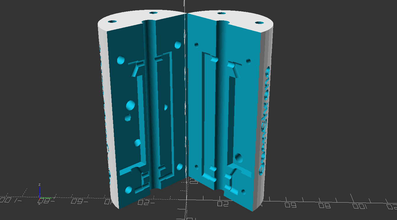
Left Half
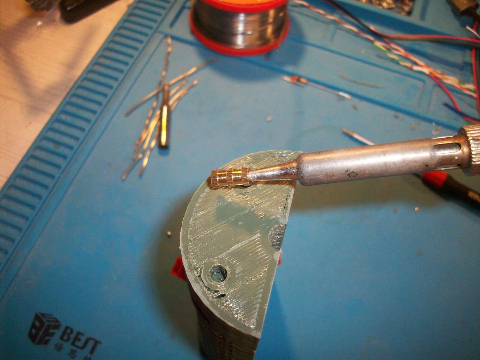
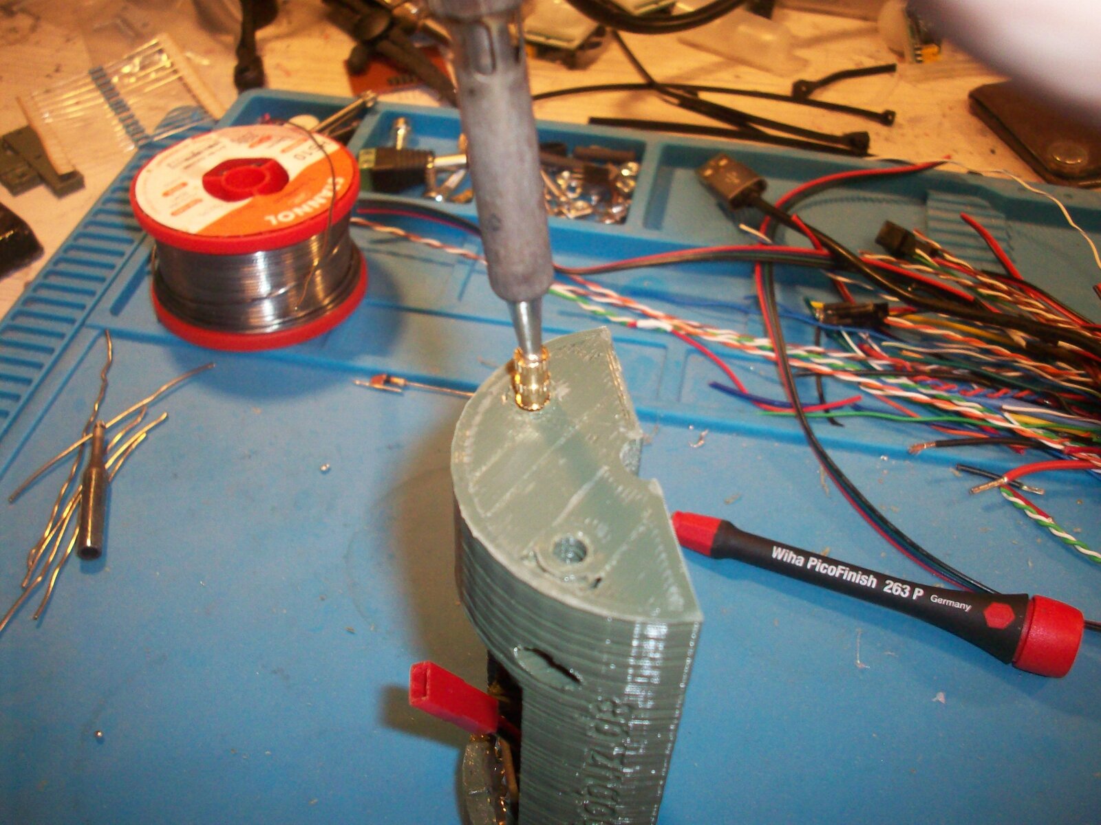
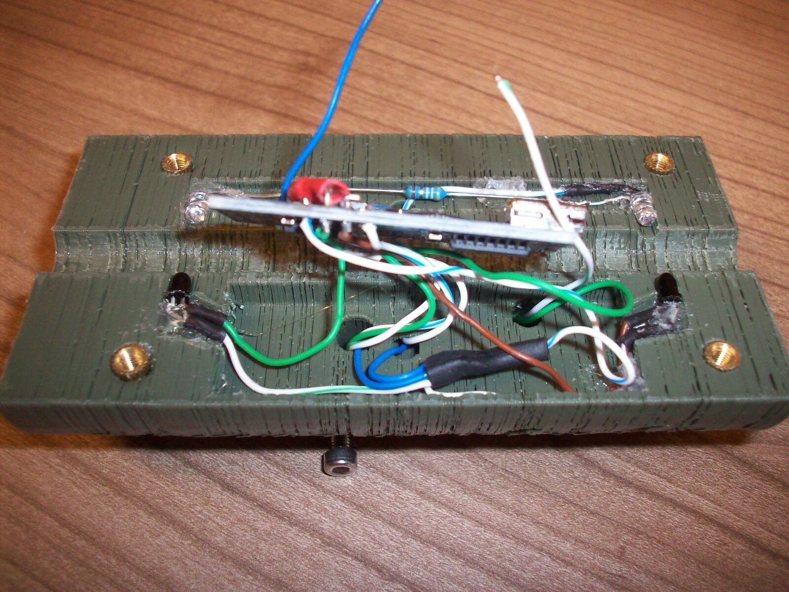
Print the parts, remove supports and do some sanding as needed. Then put in the heat-melt inserts. I recommend using a spare thick soldering iron tip. Also I put in a small grub screw and place it at the bottom of the insert. This way, any plastic that gets pushed down will not clog the thread. Push them in, use a hard flat surface to align them with the printed part, let it cool and remove the grub screw.
To connect all the parts I recommend using a thin stranded wire.
I used the cores of an old ethernet cable.
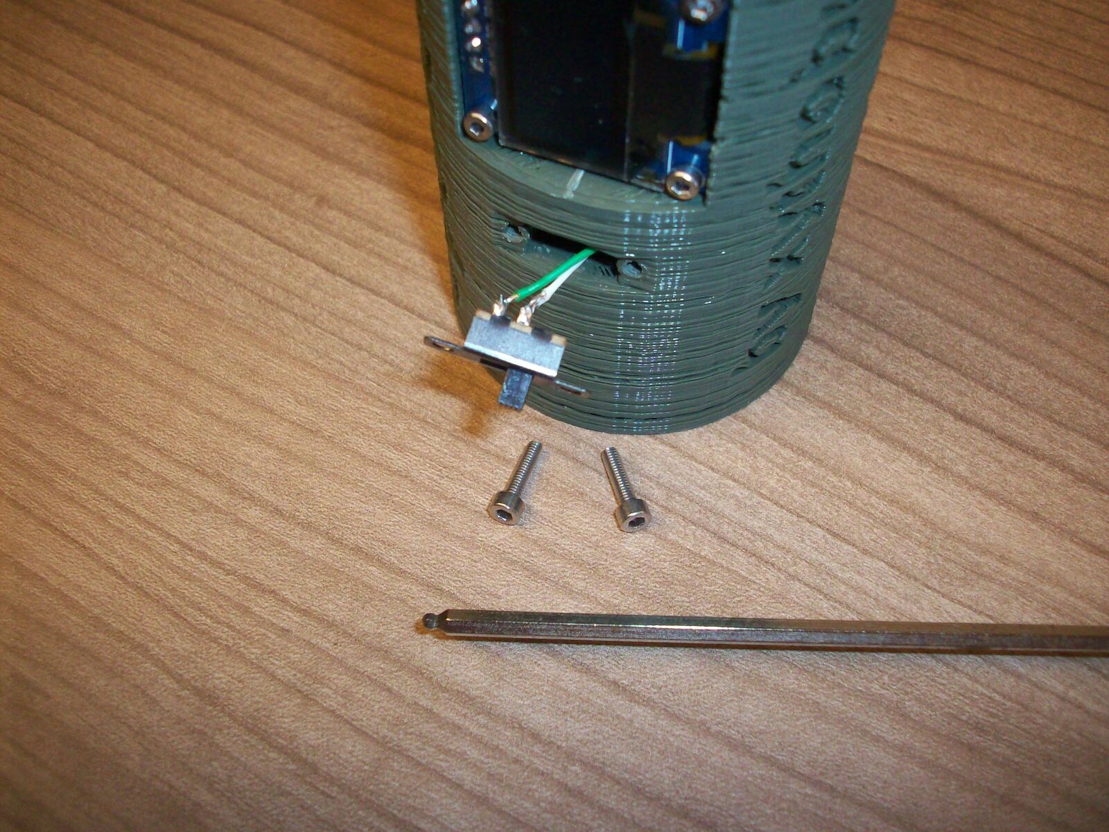
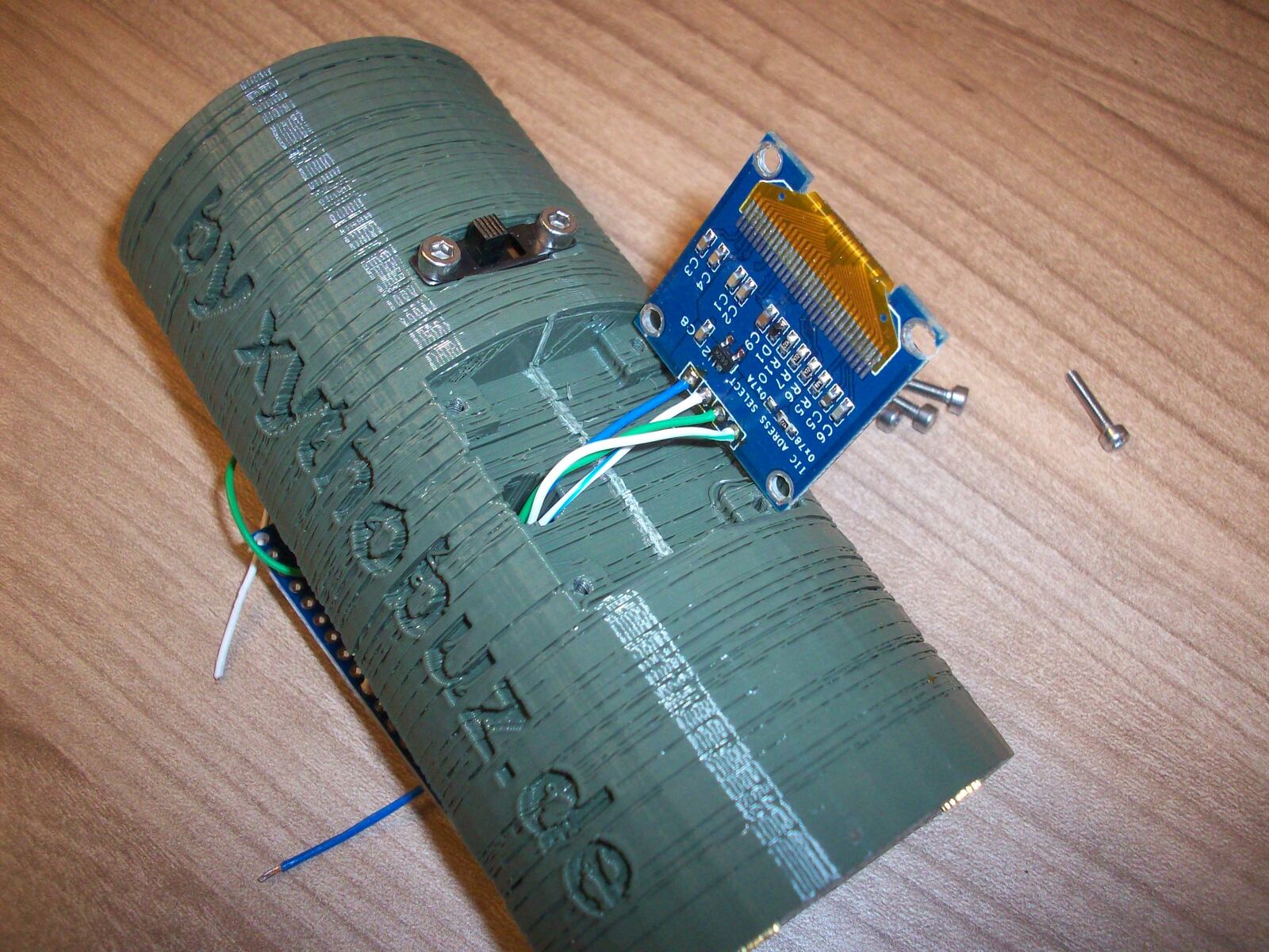
First solder wires with enough length to the OLED display and power switch.
Feed these through the printed left_half before screwing on both parts from the outside.
On the inside of the left_half you should next add the IR LEDs and phototransistors (and UV LEDs, if needed).
Pre-bend the wires of the parts to a 90 degree shape that fits the slots in the parts.
If you'd like, add some heat-shrink tubing to insulate agains potential shorts.
Next use a small amount of hotglue to fix the LEDs and transistors into their respective slots.
You need to take care to align the phototransistors and the LEDs properly. They need to look at each other as straight as possible. If there is too much deviation, and you maybe also have a resistor that limits the LED current too much, the transistor will not switch properly!
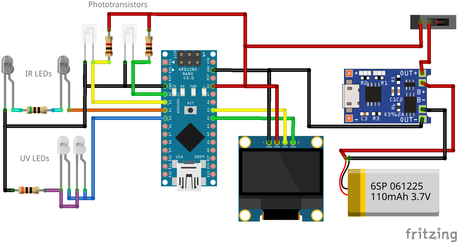
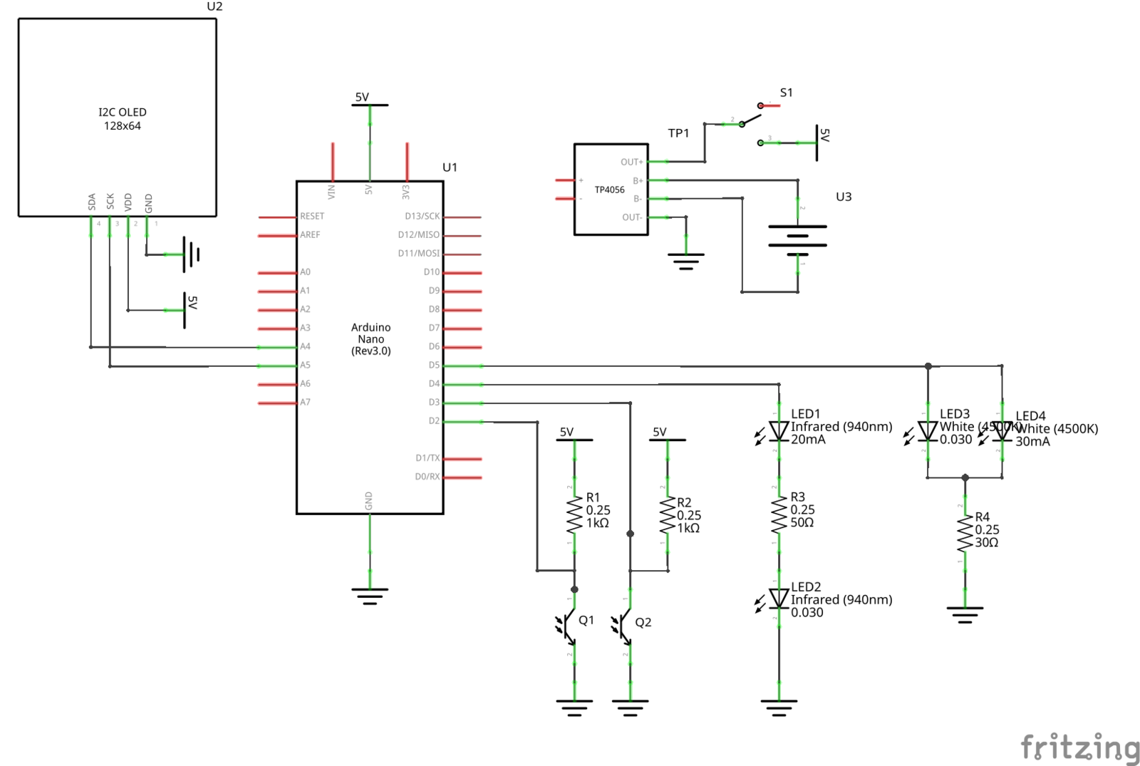
Connect the LEDs in series, as shown on the schematics.
For ease of soldering place the resistor in between the two IR LEDs.
To connect the IR LEDs to the Arduino, feed two wires through their canal in the left_half to bring them over to the other side.
For the UV LED option, you can simply route the wires along the existing channels for the IR LED wires. Only fitting the additional resistor in can be a little bit tricky.
Do the same for the phototransistors. I recommend connecting both of their Emitters, as well as all the other Ground connections (battery, OLED display, phototransistors, LEDs) together in one spot, wrapping their connection point in heat-shrink tubing. For the pull-up resistors of the phototransistors, I soldered them on top over the Arduino to the +5V pad, with heat-shrink tubing to prevent any shorts. I think this is the most space efficient solution.
Also beware to not leave too long dangling wires. This will make later putting both halves together difficult.
You should be able to build all this with 0.25W THT resistors and everything can fit if you take care to not use up too much space. If you can I recommend using SMT parts to greatly ease assembly. But just to make sure it can be done, I used THT parts.
Now everything should be connected to the Arduino. As the final step for the left half, solder two wires to +5V and GND of the Arduino respectively and leave them dangling for maybe 10mm or more. This will later connect to the right half.
Tracer Option
If you want to build the left half with the UV LED tracer option included I recommend using the existing ground connections of the IR LEDs and phototransistors.
That way you only need to run two additional wires.
I placed the 30Ω resistor on the underside of the Arduino, shielding it with some heat-shrink tubing.
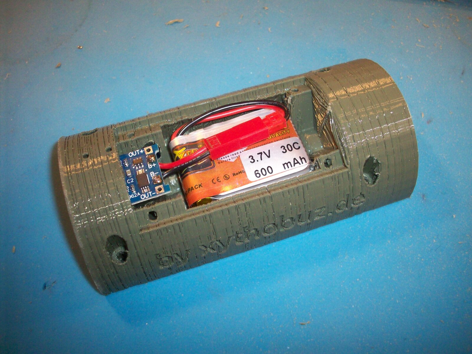
Right Half
Next we're going to prepare the right half.
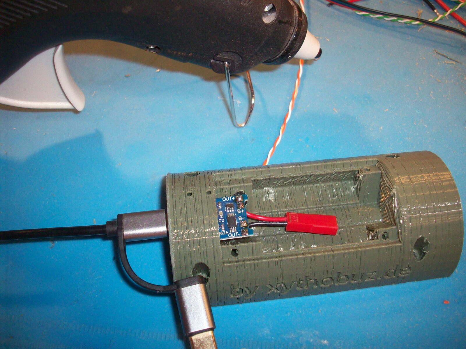
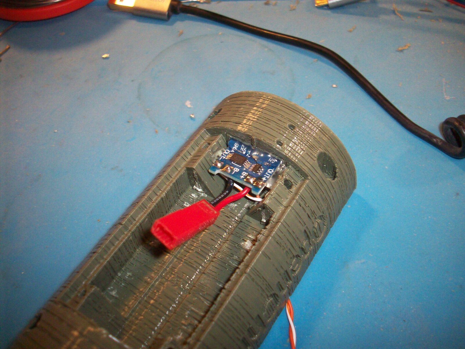
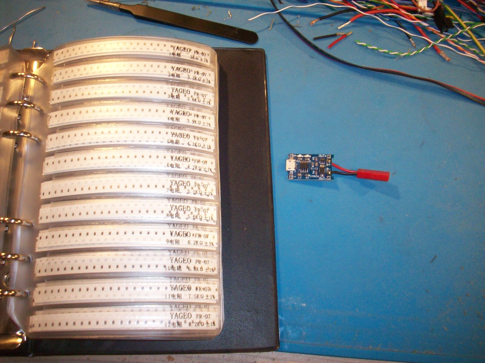
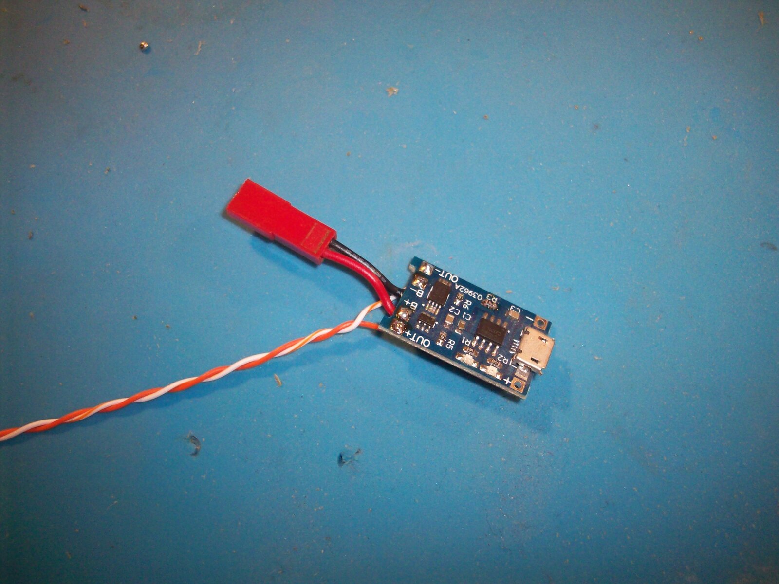
Beware: If you use the TP4056 LiPo charger board, they normally come with the charge current set to 1A with a 1.2kΩ resistor on position R3. You need to put in a higher valued resistor instead, otherwise the small battery will be charged with far too much current and the charger will get very hot. I recommend 4kΩ or more. See this page and this video for more info.
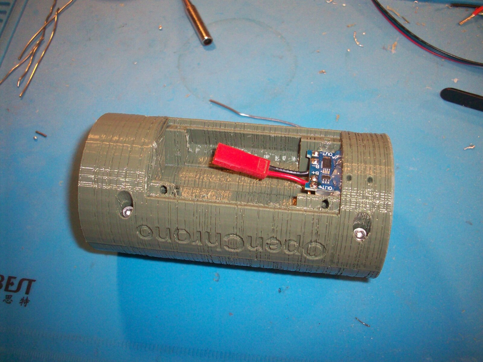
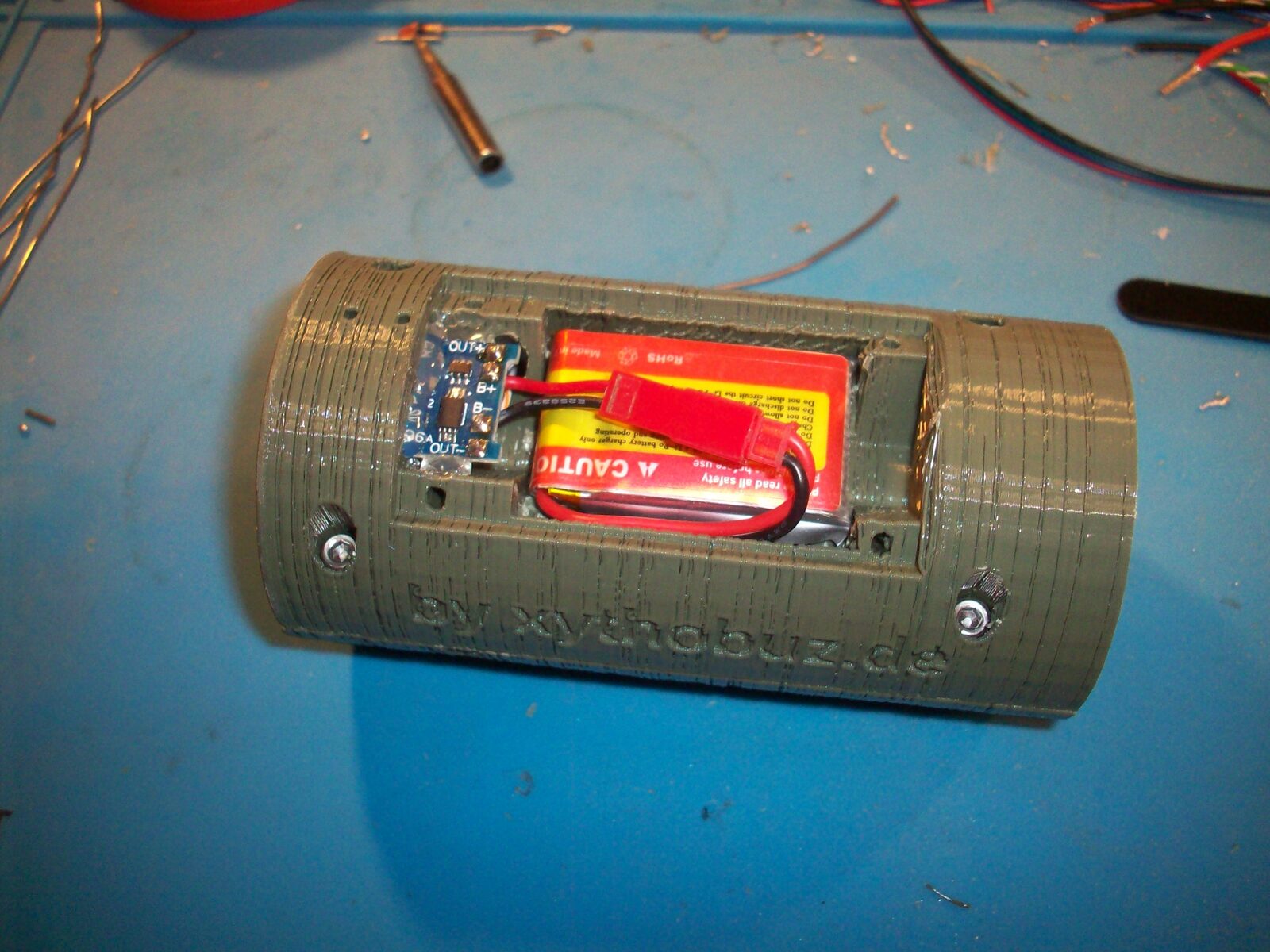
Next either solder the battery directly to the proper charging board pads, or, if you have it, use the connector that's probably already fitted to your battery, like I did. Also connect two wires to the OUT+ and OUT- pads, and feed them through the hole next to the charger board hole. Now first see if the board properly fits into its slot. If that is the case take it out again, put some dabs of hotglue in the hole, and push the board back in. You should be able to easily remove hotglue in the USB connector area while it is still warm. Then secure the board with some more glue on the sides and on top. This should hold the board firmly in place even when pushing in a USB connector!
Beware: If you are using the LiPo charger make sure to always keep the power switch in the off position while having a charging USB cable connected.
Turn the right half to the inside and cut the power supply wires to an appropriate length. Then solder them to the power supply wires of the Arduino, insulating with some heat-shrink tubing.
To flash the firmware onto your Arduino please also take a look at the "Software" section of the README.md.
Beware: Always leave the power switch in the off position when connecting a USB cable to flash the Arduino.
Finally screw both halves together, put in the battery and turn your device on. Test it by dropping a BB through the device (but beware, depending on your firmware setting this may be too low a speed to measure properly).
Attach the threaded adapter for your gun and in turn attach all this to your airsoft gun. For the first tests, I recommend supporting the weight of the device from below with your hand, depending on how your gun works and if the excess weight may damage the mechanism. Also be careful for the first test shots! If for some reason the hole through the device is not perfectly aligned with your gun barrel, the BB may skip off from the side walls and come out of the front in unpredictable directions. In that case, you will not hit what you are aiming at! So beware of your environment, wear proper safety gear and start out with a short distance to your bullet stop, increasing only slowly as you are sure everything works as expected.
Firmware
To achieve high measurement accuracy I used some of the hardware features of the AtMega328p MCU included in standard Arduinos.
To measure the impulses I'm using the two available external interrupts, INT0 and INT1. They are connected to the phototransistors and usually are on a low level when the LED shines on them as no BB passes through. When the BB passes the transistor the interrupt pins are pulled high.
So I'm triggering them on rising edges and measure the current time in the interrupt routines and set a flag.
void interrupt_init() {
    // trigger both on rising edge
    EICRA = (1 << ISC00) | (1 << ISC01);
    EICRA |= (1 << ISC10) | (1 << ISC11);

    // enable interrupts
    EIMSK = (1 << INT0) | (1 << INT1);
}

/*
 * this is supposed to be the "input" sensor,
 * the one that triggers first on firing.
 */
ISR(INT0_vect) {
    time_a = timer_get();
    trigger_a = 1;
}

/*
 * this is supposed to be the "output" sensor,
 * the one that triggers after the other sensor.
 */
ISR(INT1_vect) {
    time_b = timer_get();
    trigger_b = 1;

    // we now need to turn on the UV led
    // and make sure it will only be on shortly!
    timer_start();
    digitalWrite(UV_LED_PIN, HIGH);
}
Link to the complete file "timing.cpp" (alt 1)
For timer_get() and timer_start() I'm using another feature of AVR MCUs, their internal Timers.
The 328p has three timers.
Timer0 and Timer2 are 8bit, but Timer0 is already used by the Arduino framework to keep track of the passed milliseconds.
Timer1 is 16bit and can therefore count for the longest time, so I'm using that to measure the speed of the BBs.
To keep the interrupt routines as short and as equal-length as possible, I'm running the Timer1 all the time. It simply counts from 0x0000 to 0xFFFF and on overflow rolls back to the beginning. The clock source prescaler determines the maximum and minimum possible measurement speeds. When the external interrupts fire, they simply record the current value of Timer1. Later when both have fired and the UI code is not busy, both stored timer values will be used to calculate the time it took for the BB to travel the distance between the measurements.
static void timer1_init() {
    // normal mode
    TCCR1A = 0;

    // prescaler
#if TIMER_PRESCALER == 1
    TCCR1B = (1 << CS10);
#elif TIMER_PRESCALER == 8
    TCCR1B = (1 << CS11);
#elif TIMER_PRESCALER == 64
    TCCR1B = (1 << CS11) | (1 << CS10);
#elif TIMER_PRESCALER == 256
    TCCR1B = (1 << CS12);
#elif TIMER_PRESCALER == 1024
    TCCR1B = (1 << CS12) | (1 << CS10);
#else
#error Invalid Prescaler for Timer1
#endif
}

// ...

uint16_t timer_get() {
    return TCNT1;
}
Link to the complete file "timing.cpp" (alt 1)
static void calculate(uint16_t a, uint16_t b) {
    uint16_t ticks = 0;

    if (b >= a) {
        // simple case - just return difference
        ticks = b - a;
    } else {
        // the timer overflowed between measurements!
        int32_t tmp = ((int32_t)b) - ((int32_t)a);
        tmp += 0x10000;
        ticks = (uint16_t)tmp;
    }

    double speed = tick_to_metric(ticks);
    if ((speed >= MIN_SPEED) && (speed <= MAX_SPEED)) {
        // only register realistic velocities
        tick_new_value(ticks);
        lcd_new_value();
    }
}
Link to the complete file "OpenChrono.ino" (alt 1)
From this the speed and (given the BB weight) the energy can be calculated easily.
double tick_to_metric(uint16_t ticks) {
    // v = d / t
    double period = 1000.0 / ((double)(F_CPU / TIMER_PRESCALER));
    double time = period * (double)ticks;
    double speed = (double)SENSOR_DISTANCE / time;
    return speed;
}

double metric_to_imperial(double speed) {
    // convert m/s to f/s
    speed *= 3.28084;
    return speed;
}

double metric_to_joules(double speed, double mass) {
    // e = 0.5 * m * v^2
    double energy = 0.5 * mass * speed * speed / 1000.0;
    return energy;
}
Link to the complete file "ticks.cpp" (alt 1)
Timer2 is used for the tracer feature, to turn on the UV LEDs only for as long as needed. This could enable a future improvement where the UV LEDs could be pulsed with a far higher current to achieve more light output. To pulse the LEDs I'm only connecting the timer to a clock source when the LEDs have been turned on, with an initial value of the timer that determines how long it will take to count up to 0xFF. Then in the overflow interrupt I'm turning off both the LEDs and the Timer again.
static void timer2_init() {
    // normal mode, no clock source
    TCCR2A = 0;
    TCCR2B = 0;

    // enable overflow interrupt
    TIMSK2 = (1 << TOIE2);
}

// ...

void timer_start() {
    /*
     * the distance between the second IR sensor
     * and the UV LEDs is 7.5mm.
     * Our bullet will travel with a speed of
     * ~10m/s up to ~300m/s approximately.
     * So it will move the 7.5mm in
     * 750us to 25us respectively.
     * So it makes sense to keep the UV LED
     * on for 1ms.
     *
     * We reach exactly 1ms when counting to 250
     * with a prescaler of 64 at 16MHz.
     *
     * If you __really__ want to increase the brightness
     * of the tracer, reduce the pulse length here.
     * Then you can also reduce the UV LED resistor for
     * higher currents, according to the datasheet of
     * your UV LED.
     * Make sure to keep within 40mA the AVR GPIO can provide.
     * Otherwise you need to add a transistor for switching.
     */
    const static uint8_t pulse_length = 250;

    // initial value we count up from
    TCNT2 = 0xFF - pulse_length;

#ifdef DEBUG_LONG_UV_TIME
    led_runs = 0;
#endif

    // prescaler 64
    TCCR2B = (1 << CS22);
}

ISR(TIMER2_OVF_vect) {
    /*
     * When a BB is only dropped through the device it moves
     * with something like 0.1m/s to 1m/s of velocity.
     * So in this case it only moves the 7.5mm to the UV LEDs
     * in 75ms to 7.5ms respectively.
     * So our 1ms pulse is not illuminating it at all!
     * In this case, we have to increase our pulse time by
     * approx. factor 100.
     */
#ifdef DEBUG_LONG_UV_TIME
    led_runs++;
    if (led_runs < 100) {
        // keep running for another millisecond
        TCNT2 = 0xFF - 250;
        return;
    }
#endif

    // turn off UV LED
    digitalWrite(UV_LED_PIN, LOW);

    // and also stop timer
    TCCR2B = 0;
}
Link to the complete file "timing.cpp" (alt 1)
In the main-loop I'm simply updating the LCD to show the measured values. This is very easy to implement using the great u8g2 library.
If you're interested I recommend taking a look at the code. I think it should be relatively easy to understand and well commented 😅
Possible Future Improvements
As usual I was mostly using parts that I already had. That explains some strange design decisions, like using cylindrical screws for the battery compartment lid, which honestly look and feel ugly and stand out from the device.
I'm sure it is also possible to make better use of the space inside the device and make wiring much easier that way.
Also the tracer feature has been kind of an afterthought. I have no real use for it and it does not work the way it currently is dimensioned. I also don't think it's realistic to take this bulky device onto a field, but who knows, I'm not really into that.
To be quite honest, I'm happy with the device as it is now. But I'm always open to feedback and pull requests of course, especially ones improving the tracer option 😉
Potential Other Uses
One thing I'd like to talk about is using this device for measuring other things besides Airsoft BBs. It is definitely feasible to use OpenChrono to measure the speed of air rifle pellets, and this is something I would be interested in as well. Unfortunately my air rifle does not have a threaded barrel, so attaching the device with proper alignment will be difficult.
Speaking from a measurement perspective, the phototransistors and the Arduino are easily able to measure higher speeds. 500m/s or more should be no problem. So it is possible to measure much faster projectiles, like real bullets for example. Beware however about the 3D printed housing. I'm not sure if it would be able to survive either the pressures involved or the impulse of firing. This could maybe partly be fixed by adding depressurization holes to the device. All the hot gases coming out of a real gun will probably also be problematic, both for the plastic and for the optical measurement method.
But all this is not something I can or want to test, and I also do not recommend you do it, either! 👮
Links
You can find all the source code and design files for OpenChrono on Codeberg. The project is also mirrored on GitHub.
If you decide to build it yourself I would be interested in any kind of feedback!
License
OpenChrono is licensed under the GNU General Public License.
Copyright (c) 2022 Thomas Buck <thomas@xythobuz.de>

OpenChrono is free software: you can redistribute it and/or modify
it under the terms of the GNU General Public License as published by
the Free Software Foundation, either version 3 of the License, or
(at your option) any later version.

OpenChrono is distributed in the hope that it will be useful,
but WITHOUT ANY WARRANTY; without even the implied warranty of
MERCHANTABILITY or FITNESS FOR A PARTICULAR PURPOSE.  See the
GNU General Public License for more details.

You should have received a copy of the GNU General Public License
along with OpenChrono.  If not, see <https://www.gnu.org/licenses/>.
More Pictures