Trackball
3D printed mouse replacement with Raspberry Pi Pico and PMW3360
Project published on February 12, 2023.Recent activity in the repo: 
...back to Input Devices overview
For some years I have been using Trackballs from Logitech, first the M570 and then the MX Ergo. But of course we could also build our own!
So because Philipp and I were already looking into building a keyboard with a trackball included, I decided to first get my feet wet by building a stand-alone version.
It's made with a PMW3360 optical mouse sensor and a Raspberry Pi Pico. The case is 3D printed and was designed in OpenSCAD.
As usual the project is released as free and open-source software / hardware. You can find everything you need to build it yourself in the git repository!
Table Of Contents
- Part Selection
- 3D Design
- Firmware Development
- Wiring
- Sensor Problems
- First Prototype
- Improvements
- User Experience
- License
- More Pictures
Part Selection
Before embarking on this project some decisions and orders had to be made.
To control everything I decided to go with the Raspberry Pi Pico / RP2040 microcontroller board. It is the hot new thing on the block and I wanted to try out both the hardware and the SDK. It's also used extensively in the DIY keyboard community and already has great support in lots of open source software.
Another big question was which mouse sensor to use. There are different types of sensor, either "optical" using an IR LED, or "laser". Common choices for DIY projects are the PMW3360 or PMW3389 optical sensors, or the ADNS-9800 laser sensor. All of them are available on breakout boards from JACK Enterprises on Tindie. Unfortunately the shipping costs to Europe are very high, so I had to find another solution.
Apparently the requirements for trackballs are not as high as for gaming mouses, they are normally used with much lower resolutions. Because of this, and also because of price and availability, I decided to go for the PMW3360. The chip can be bought on AliExpress, including the lens assembly, for around 15€.
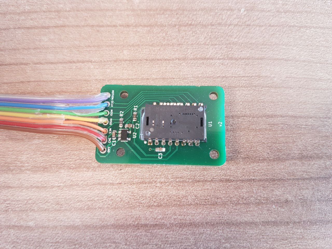
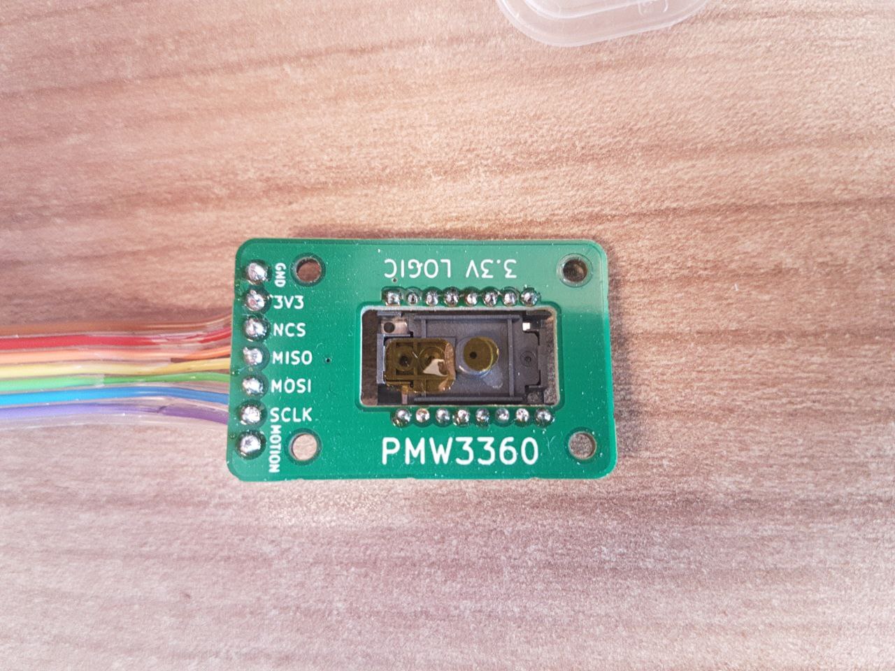
To properly use it also requires some kind of breakout board with a voltage regulator, as the sensor needs ~2V supply voltage. Fortunately the IOs can be used with 3.3V devices like the RP2040. Many designs can be found on GitHub, like "Ogen" from JeremyBois or "PMW3360" from kbjunky.
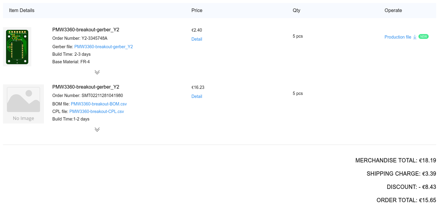
I decided to go with "pmw3360-breakout" by jfedor2. It is the most minimalistic and it also includes all required files to get the board pre-assembled from JLCPCB. With their usual promo I got 5 boards produced and assembled for just 15.65€, including shipping. This is unbelievable to me.
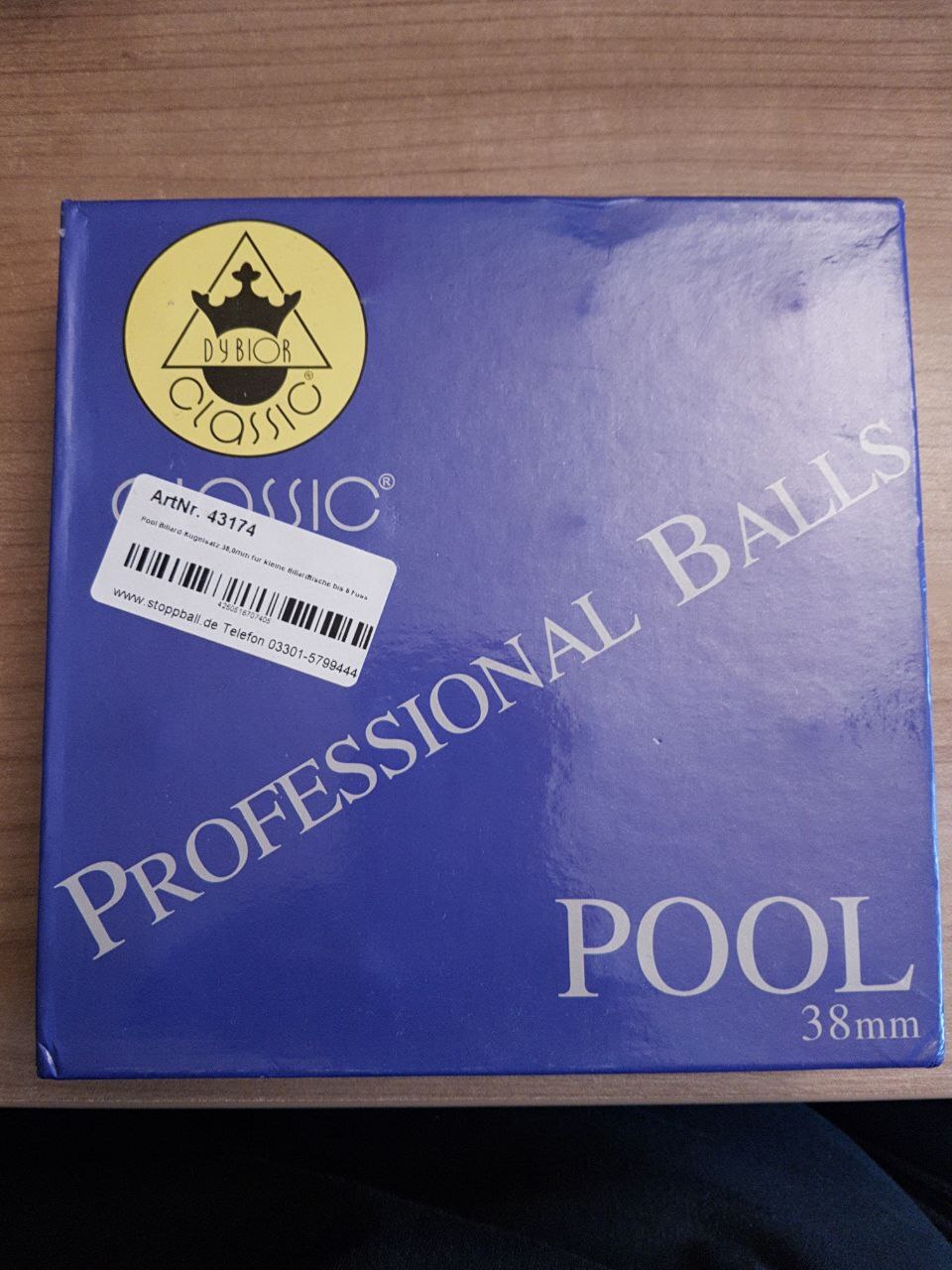
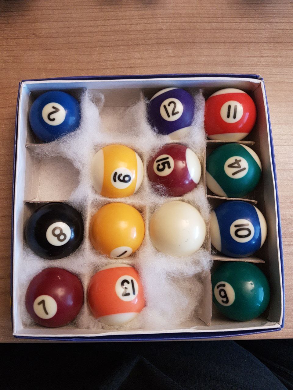
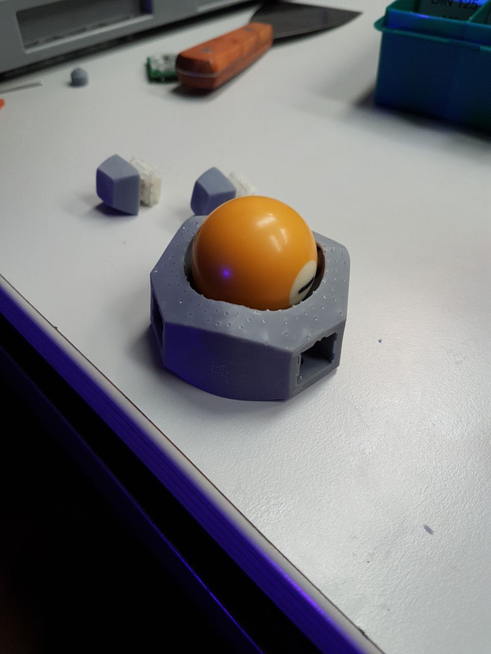
To be able to call this a trackball, we also need some kind of ball or sphere of course. Many people go with the smallest regulation billard balls with a diameter of 38mm. These can be sourced relatively easily and are usualy flat enough, so I got some. This turned out to be a bit of a problem, however, more on that later.
To get the ball rolling smoothly we also need some kind of mount or bearing surface. There are different options for this, nicely detailed on Reddit and GitHub by "Wimads". Because of this I decided to go with Si3N4 static bearing balls with a diameter of 3mm. I got 20 from eBay for ~5€.
For the switches I decided to go with Cherry MX keyboard switches, simply because I had them available. They are not optimal with their long key travel, I plan to change it in the future, but you also kinda get used to them.
| Part | Count | Description | Cost |
|---|---|---|---|
| µC | 1x | Raspberry Pi Pico | 4.10€ |
| Sensor | 1x | PMW3360 (chip and lens) | 11.83€ |
| PCB | 1x | PMW3360 Breakout Board | 3.13€ |
| Ball | 1x | 38mm billard ball | 1.37€ |
| Bearing | 3x | Si3N4 3mm sphere | 0.72€ |
| Switch | 4x | Cherry MX compatible | 1.03€ |
| Keycap | 4x | From old keycap set | 0.00€ |
| Insert | 4x | M3 od=5mm l=6mm | 0.00€ |
| Screw | 4x | M3 l=8mm | 0.00€ |
| Screw | 8x | M2 l=6mm | 0.00€ |
| Screw | 3x | Grub screw M3 l>=4mm | 0.00€ |
| Sum | 22.18€ |
Note: some parts are only sold in bulk. Therefore, if you only want to build a single trackball, it will be more expensive than the sum listed above. What you see on top is the actual price I paid for the parts, reduced to the amount required for a single device. Also some parts, like screws or 3D printing materials, I consider as normal parts of a workshop, so they are not added to the cost either.
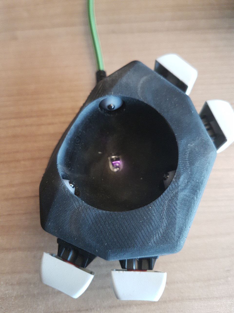
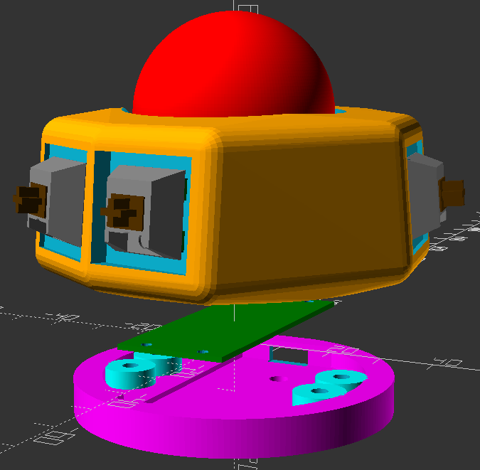
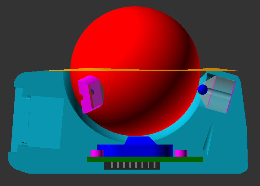
3D Design
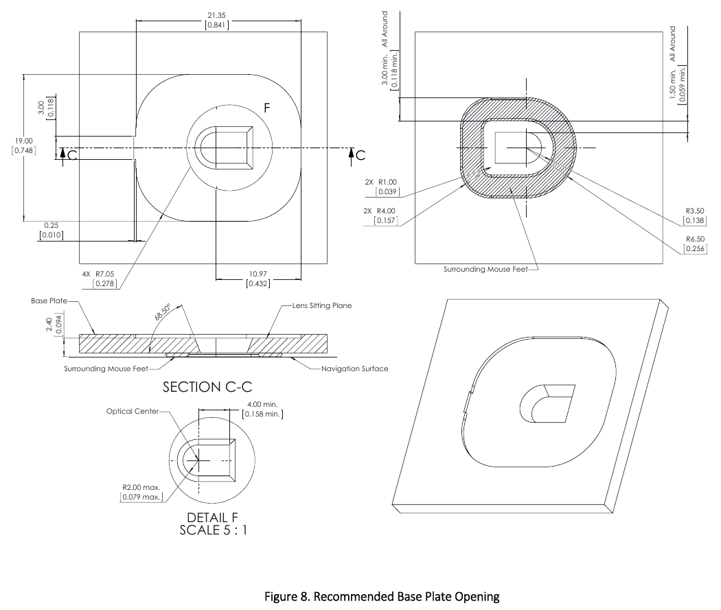
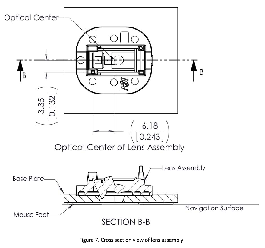
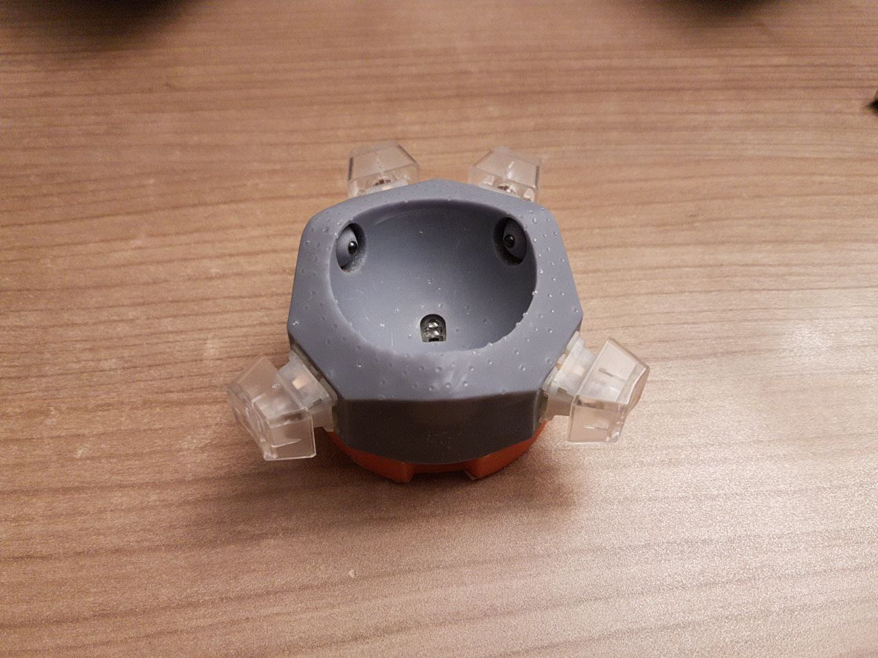
The most important part of the 3D design is the mounting of the sensor and lens assembly in relation to the tracking surface, in our case the ball. The datasheet has lots of dimensional drawings which kind of hide all the important measurements somewhere in there.
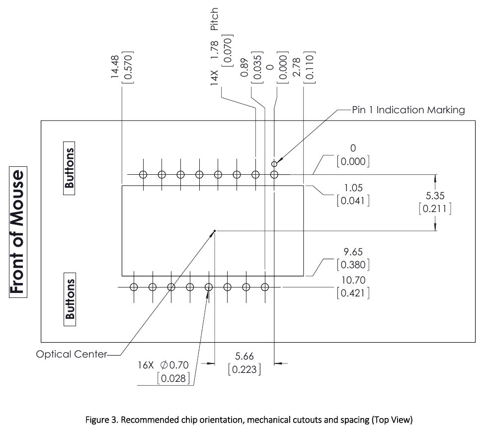
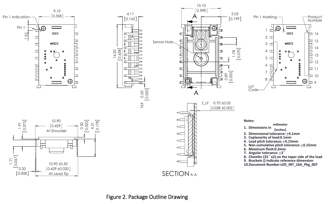
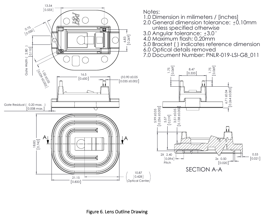
I took great care and tried to design everything according to the specifications.
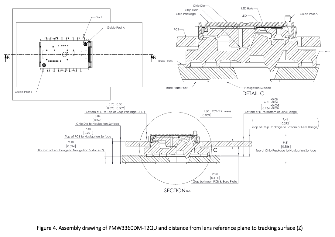
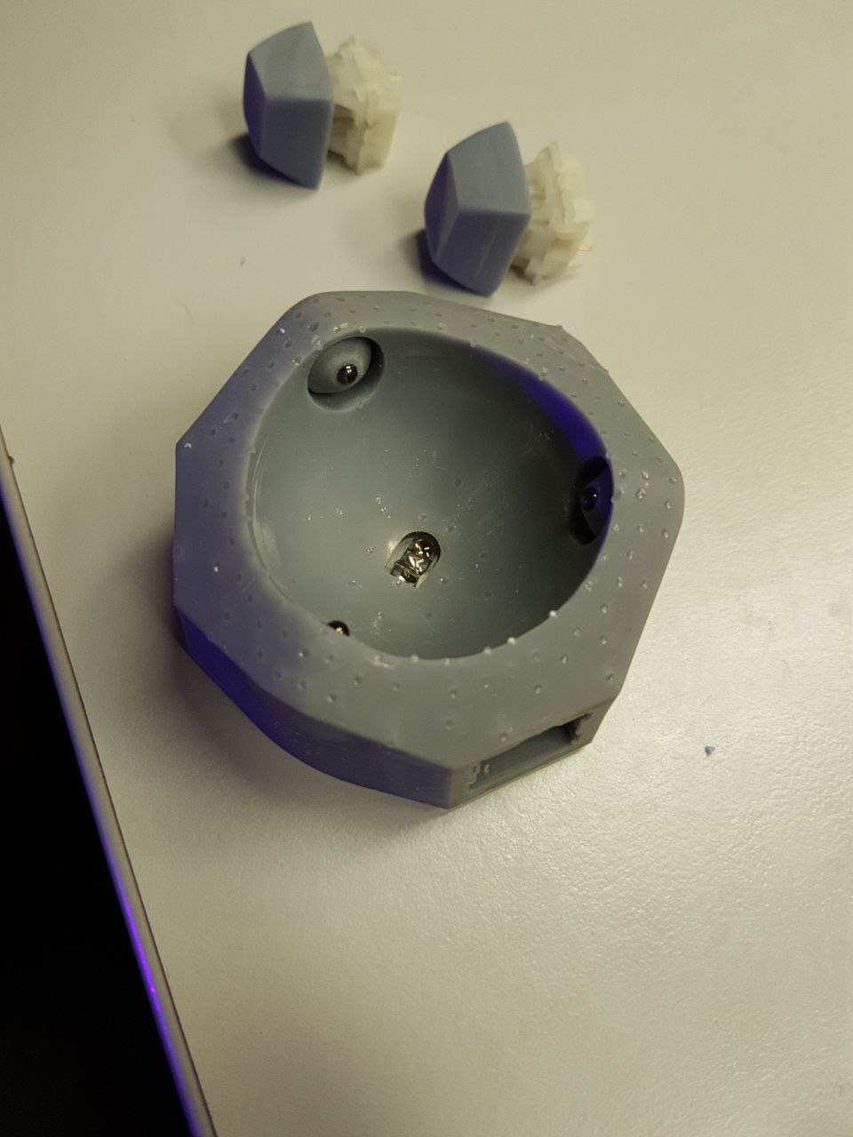
The static bearing balls are push-fit mounted inside the "roller holders". Printing this part is a bit tricky. Including the ball it should have a total height of 10mm. With my FDM printer it was 0.1mm too small, so I added an adjustment parameter in the design. Later iterations were always printed on SLA printers, where the adjustment had to be set back to zero.
So if you want the distance to be perfect, measure the printed and assembled part and adjust accordingly. Although I think small deviations shouldn't matter too much. The sensor has a relatively large range of useable distances.
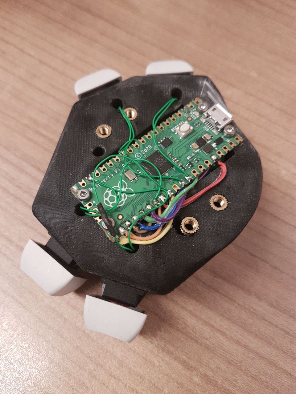
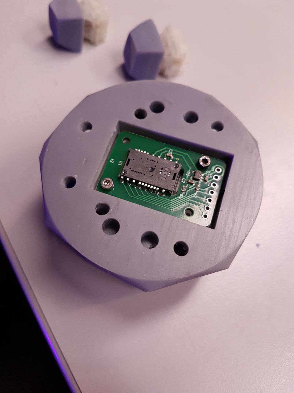
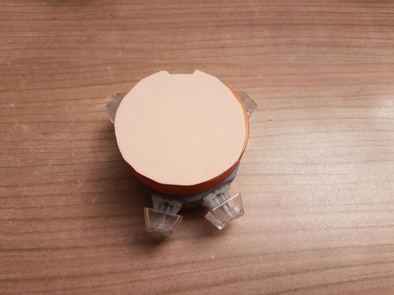
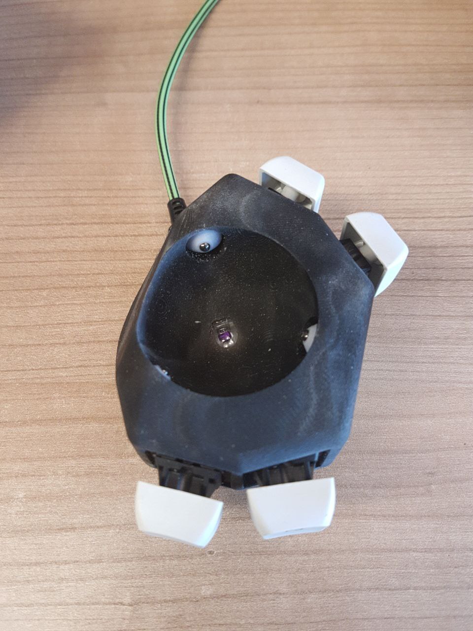
The roller holders are kept in place with a grub screw for each. Then the sensor can be screwed into the top housing first, followed by the Pi. The bottom part is just a lid, without any parts screwed into it.
Unfortunately the design is relatively unwieldy in OpenSCAD.
Even the preview render takes dozens of seconds, with a very sluggish UI afterwards.
Rendering takes ¾ of an hour on my machine.
For development the $fn parameter can be set to a lower value.
That helps somewhat.
Firmware Development
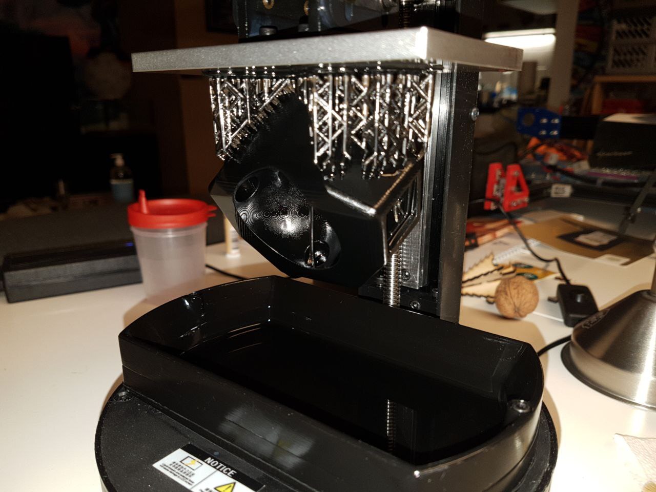
Before designing and printing the complete device I made a small test bed to hold the sensor and ball.
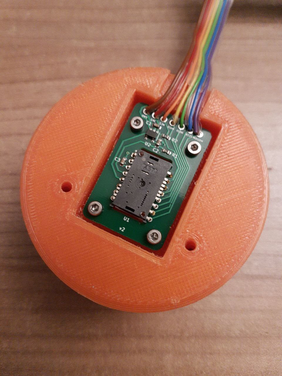
With this initial "engineering sample" built I could continue with development of the firmware. This was basically my christmas holiday project in 2022.
Interfacing with the PMW3360 chip is a bit more difficult than I initially expected. Of course everything is confidential and proprietary, but you can find leaked datasheets on the internet. It describes everything pretty well, including pinout and electrical characteristics, which were already taken care of in the breakout board. And it also describes the SPI communication interface. The only problematic part is the so-called SROM.
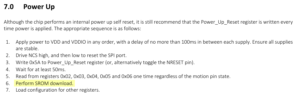
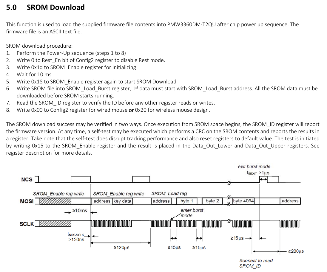
The chip requires a binary blob to be loaded on every power up, otherwise it won't work. Fortunately this was also leaked or sniffed (I'm not sure), version 4 is available here or here, for example. So I've included it in my firmware as well. Not all of the fancy functionality is included in this V4 firmware blob, but it is enough for normal mouse operation.
Contrary to that I'm very happy with the RP2040 / Raspberry Pi Pico ecosystem. The hardware seems well documented without having to go completely in-depth into the CPU datasheets. And the SDK similarly seems well thought-out and implemented.
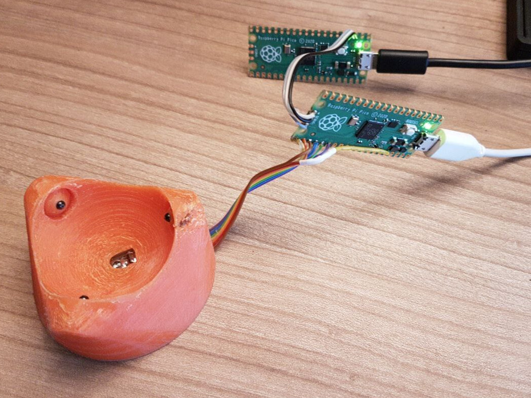
I was especially delighted with the ability to simply use a second Pico as a debugging dongle instead of needing an ST-Link or similar hardware.
For the USB device implementation the Pico SDK includes TinyUSB. From the Pico SDK I based my work on their HID Composite example ported from TinyUSB, as well as the CDC MSC example directly from TinyUSB.
This was very comfortable to use. From a past project I'm familiar with the pain of writing custom USB HID descriptors. Fortunately this is all handled by TinyUSB. You just need to pass the appropriate delta values for the mouse axes.
I combined the examples to have the device act simultaneously as a human input device, and serial port and mass storage device for debugging. Of course I only developed and tested the device on my Linux machines initially. But I have now also tested it with Windows, and it works fine there as well. All functionality can be accessed without any driver installation.
For the debug mass storage I also had to add some kind of file system. To do this I used the FatFs library. I simply reserved a bunch of memory in RAM that acts as the disk device. Before it is mounted by the user, the disk is formatted and filled with the required data. Then the host can mount it and read the files.
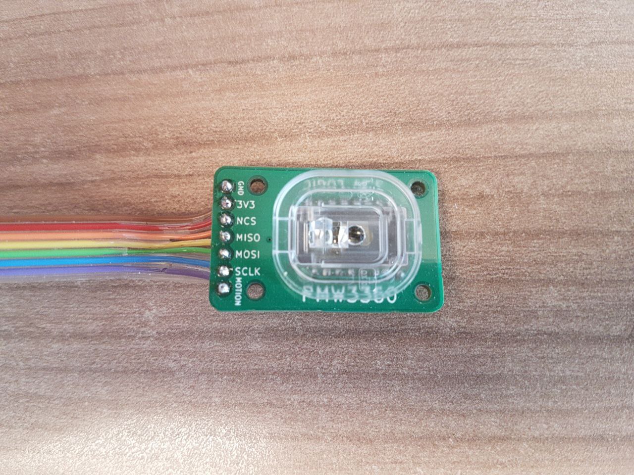
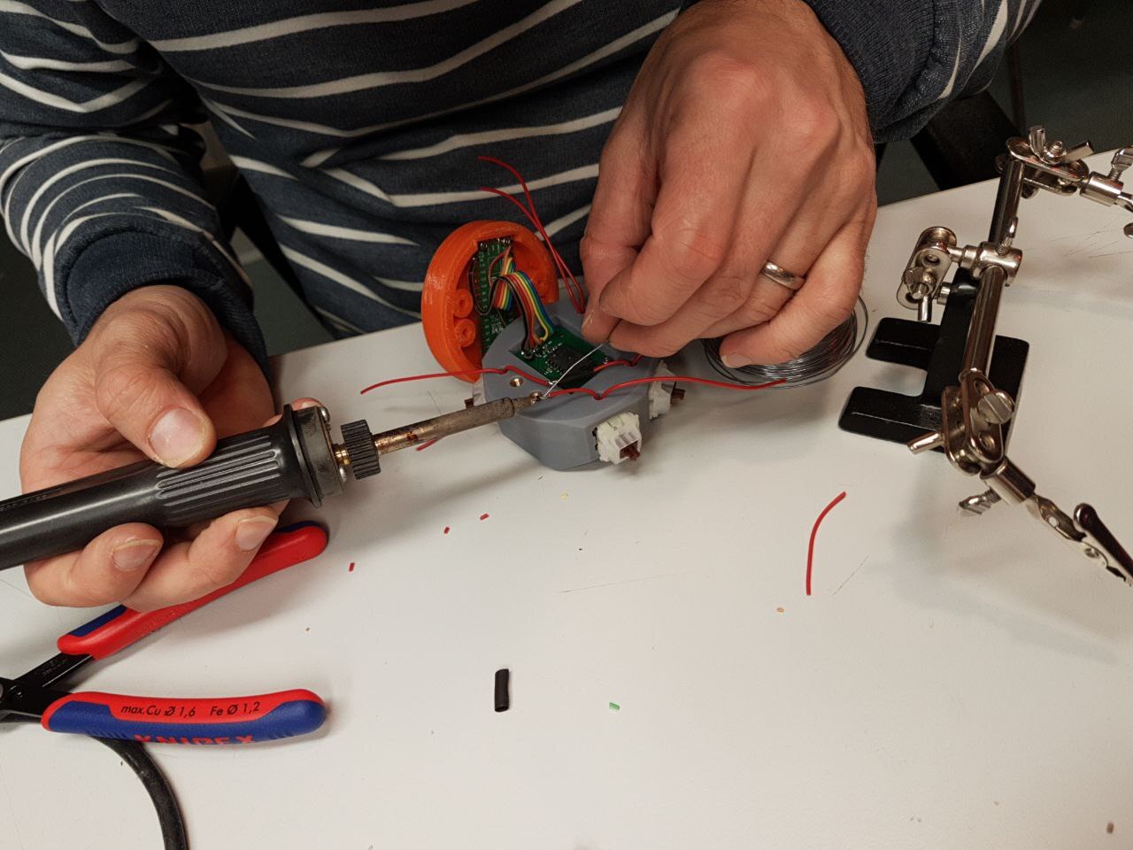
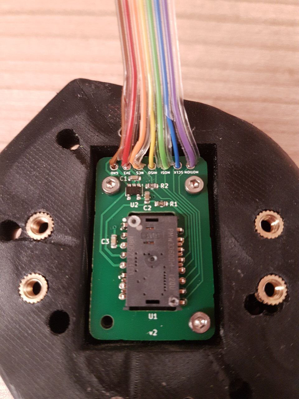
Wiring
Wiring up the device is very easy, especially because the RP2040 provides great flexibility in its use of the GPIOs and the hardware periphery, in our case SPI.
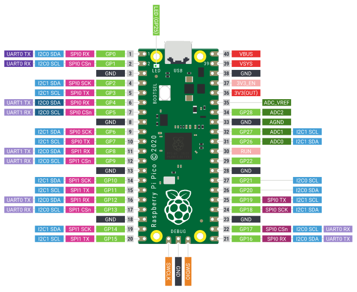
The SPI interface of the PMW3360 needs to be connected to one of the SPI interfaces of the Pico. But which one you use is not important and can easily be changed in the code. By default it uses the standard SPI0 pins.
GPIO 16 (pin 21) MISO -> MISO on PMW3360 board
GPIO 17 (pin 22) CS   -> NCS on PMW3360 board
GPIO 18 (pin 24) SCK  -> SCK on PMW3360 board
GPIO 19 (pin 25) MOSI -> MOSI on PMW3360 board
GPIO 20 (pin 26)      -> MOTION on PMW3360 board
   3.3v (pin 36)      -> VCC on PMW3360 board
    GND (pin 38)      -> GND on PMW3360 board
GPIO 21 (pin 27)      -> Switch (back button)
GPIO 22 (pin 29)      -> Switch (middle button)
GPIO 26 (pin 31)      -> Switch (left button)
GPIO 27 (pin 32)      -> Switch (right button)
The switches use the internal pull-up resistors in the RP2040 GPIOs. So they should be wired active-low, with their common connection to GND.
Sensor Problems
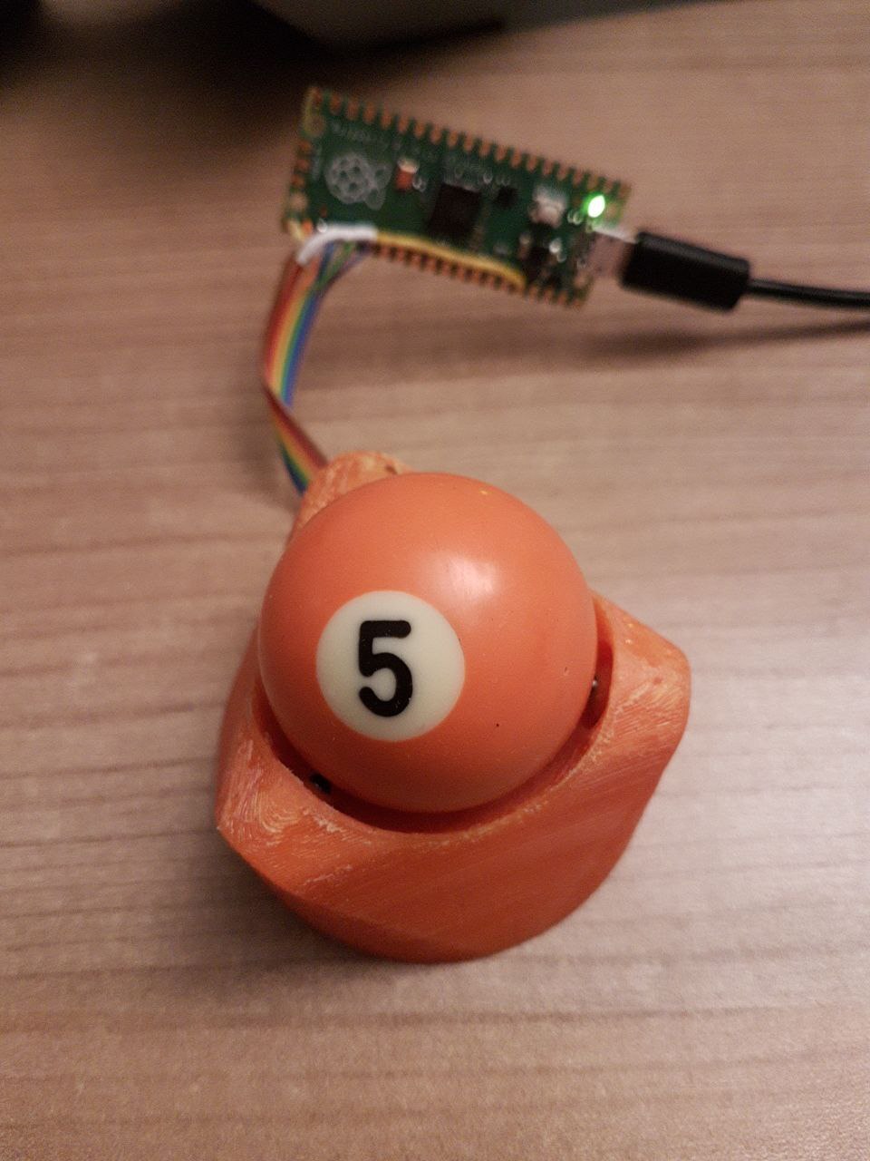
With the firmware mostly done I hoped to be able to use the device immediately. But it didn't quite work. When I ran my finger over the lens the sensor moved erratically, but no movement was seen with the white ball I initially tested with. Only after switching to other colors I noticed that they behave differently. So there was some investigation required.
Besides the X and Y values you get a bunch of other stuff with each sensor data sample. I added functionality to dump these and made a small Python script to visualize them.
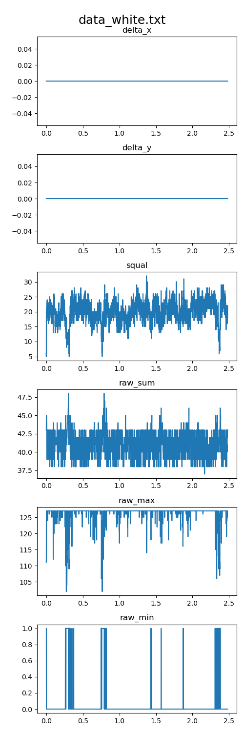
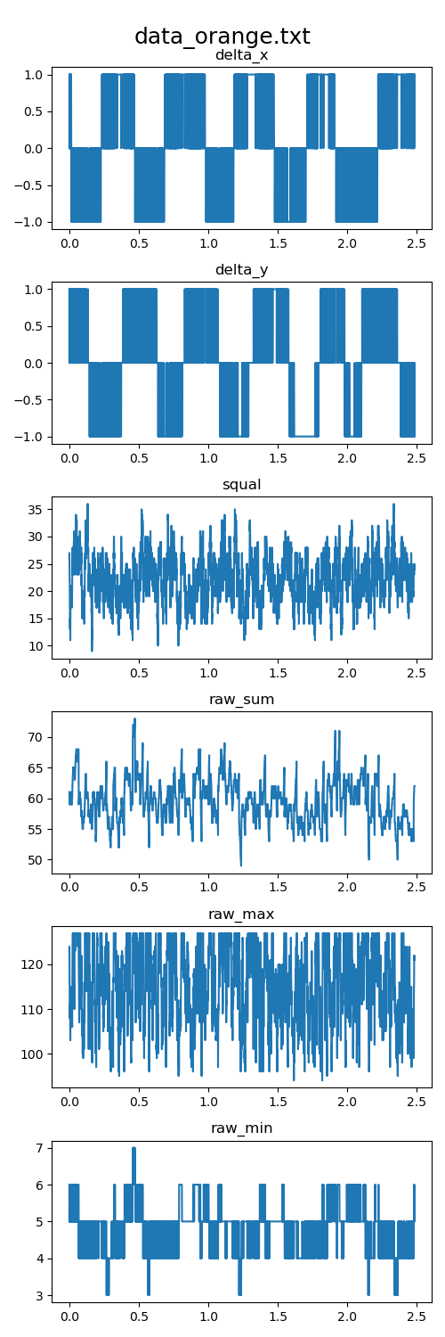
With the white ball you see no movement at all, with the orange ball there is movement, but there is no immediately obvious difference in the other datapoints.
The PMW3360 also has a "Frame Capture" mode. This can be used to grab a full picture of what the image sensor is seeing. Using it overwrites the SROM firmware, so the sensor has to be re-initialized afterwards. I had some problems with this mode. For some reason I'm not able to properly reset the sensor after capturing a frame. It no longer reports the correct SROM ID and only a power-cycle fixes it. But the frame data can be read properly and I made a Python script to visualize it.
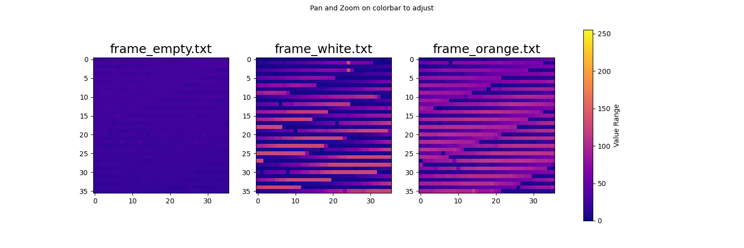
I'm not sure what exactly is going on with the strange lines visible in the pictures. I can't find any bug on the visualization side, but I won't rule that out fully. But like with the data visualization above, there is no obvious difference between the different colored balls.
While producing some pretty pictures, this approach of analyzing the data didn't really bring us any closer to a working trackball.
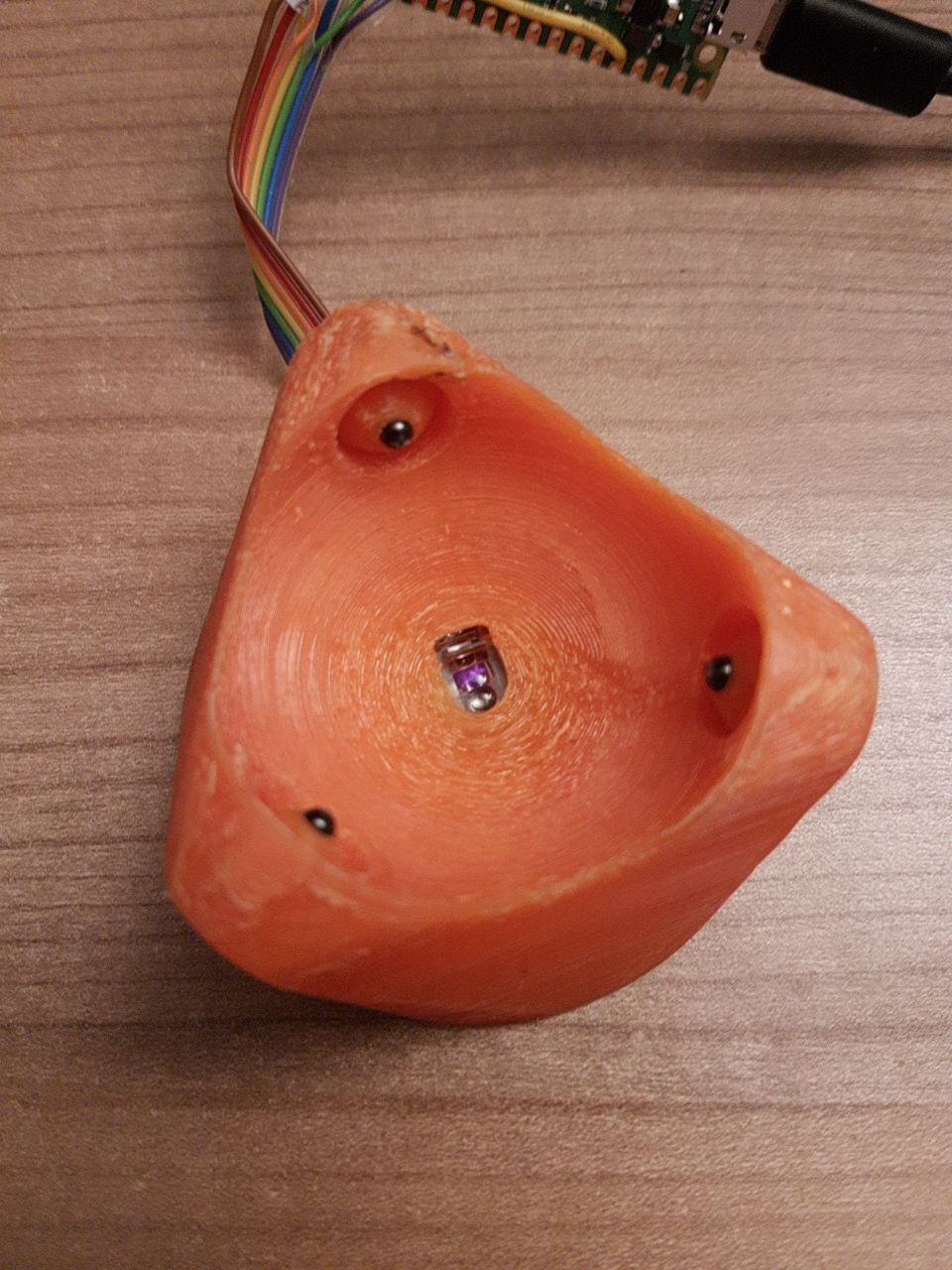
But then Philipp had the idea that saved the day. From the factory the PMW3360 sensors come with two small pieces of kapton tape over the optical inlet and outlet holes in the chip package. Removing them solved all issues.
Now all billard balls work fine, regardless of their colour. Even the white ball works without any problems. With the electronics and the firmware ready, we could now move on to refining the mechanics.
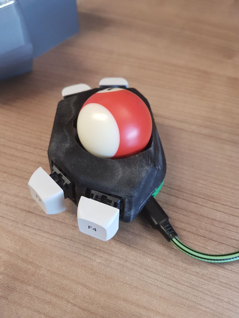
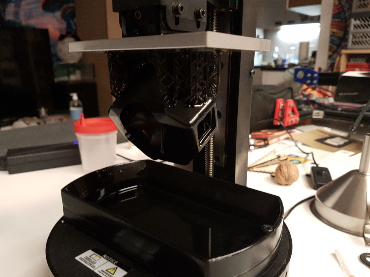
First Prototype
The first top case was printed on Philipps Anycubic Photon Mono 4K SLA printer with Anycubic Standard Resin + Grey. This turned out to not be the best choice. The resin is very brittle after curing, so after pressing the switches in for the first time, and pulling on them, small parts of the print immediately broke off. So I had to super-glue the switches in place.
Also because it's not a thermo plastic, the heat melt inserts can not be placed in the usual way. We also used super glue for these, which worked great.
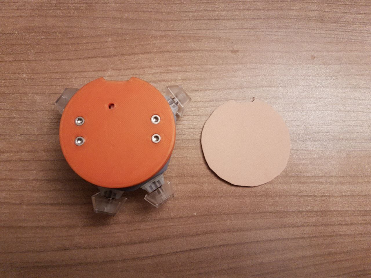
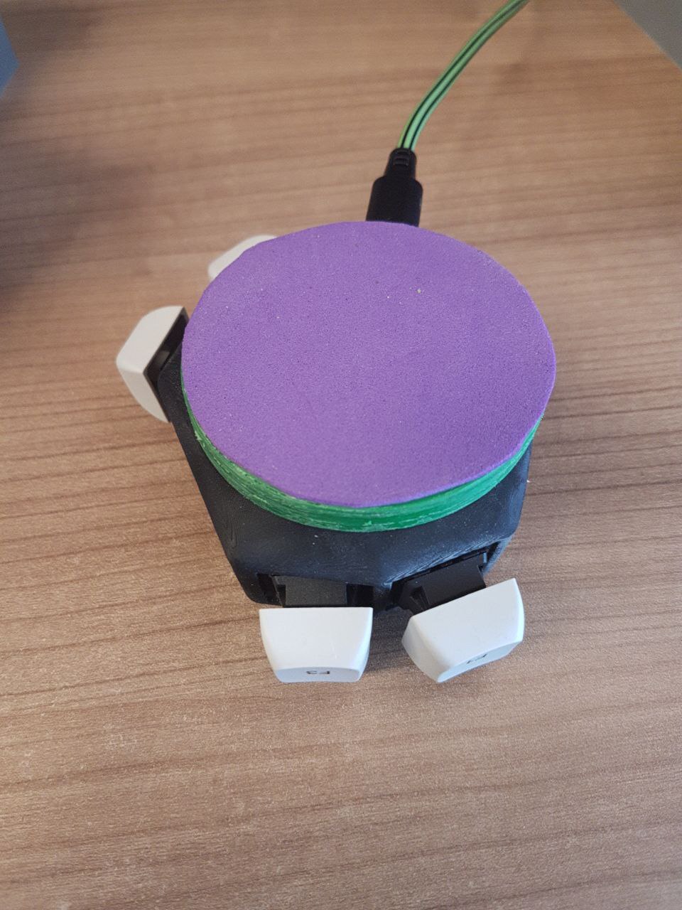
The PETG printed bottom case was very slippery on a hard table surface. So I cut a piece of self-adhesive spongy rubber to the proper size and put it on the bottom. This increases friction by a fair amount, but is not yet optimal. I will have to try out some other materials.
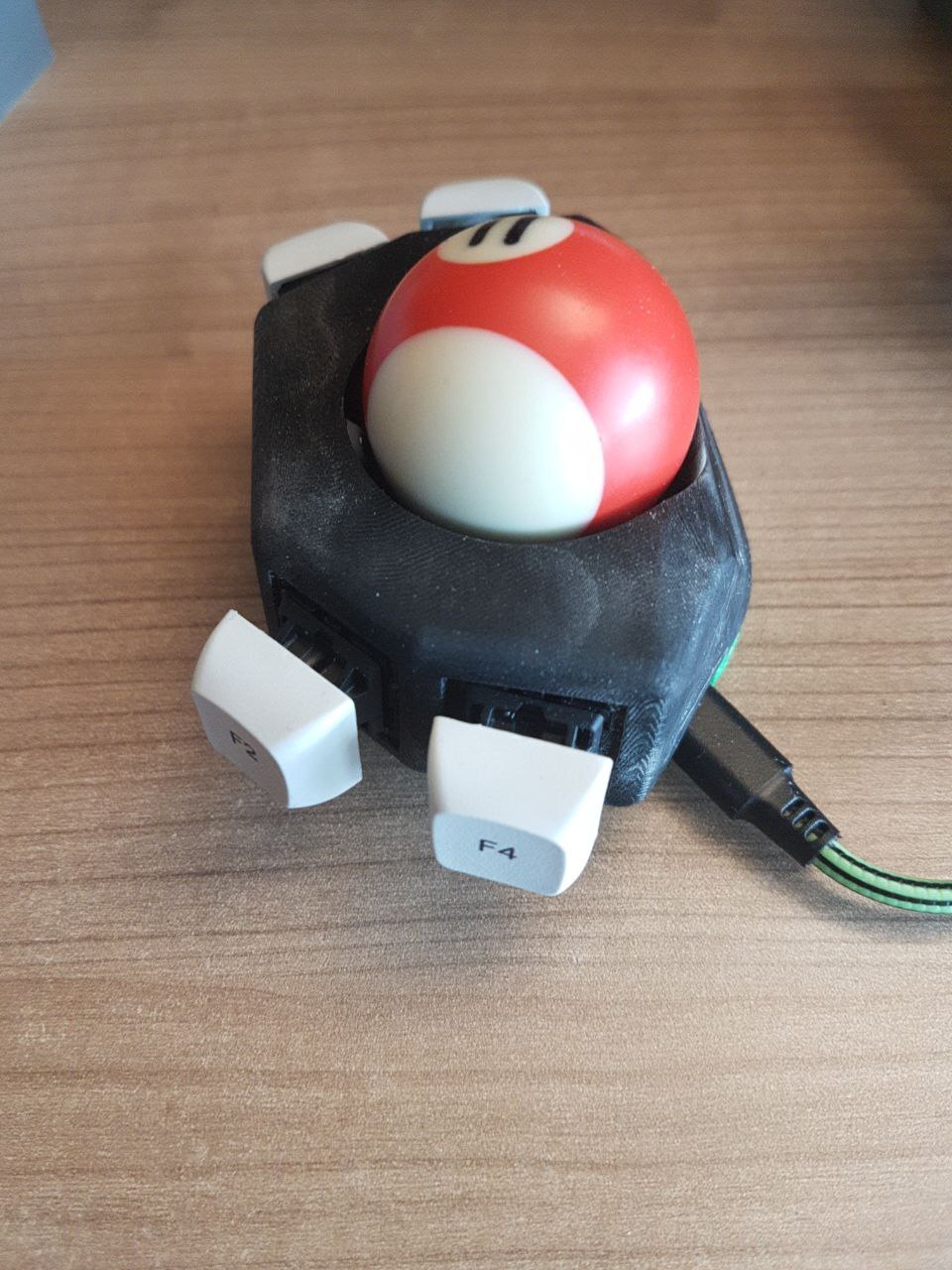
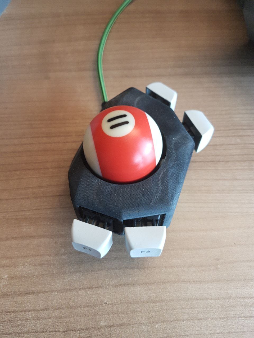
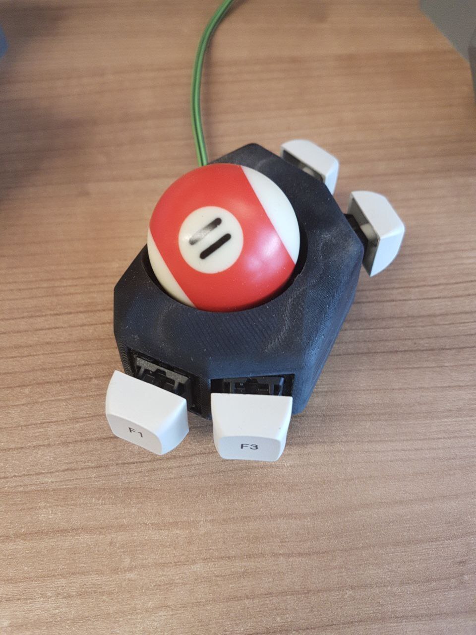
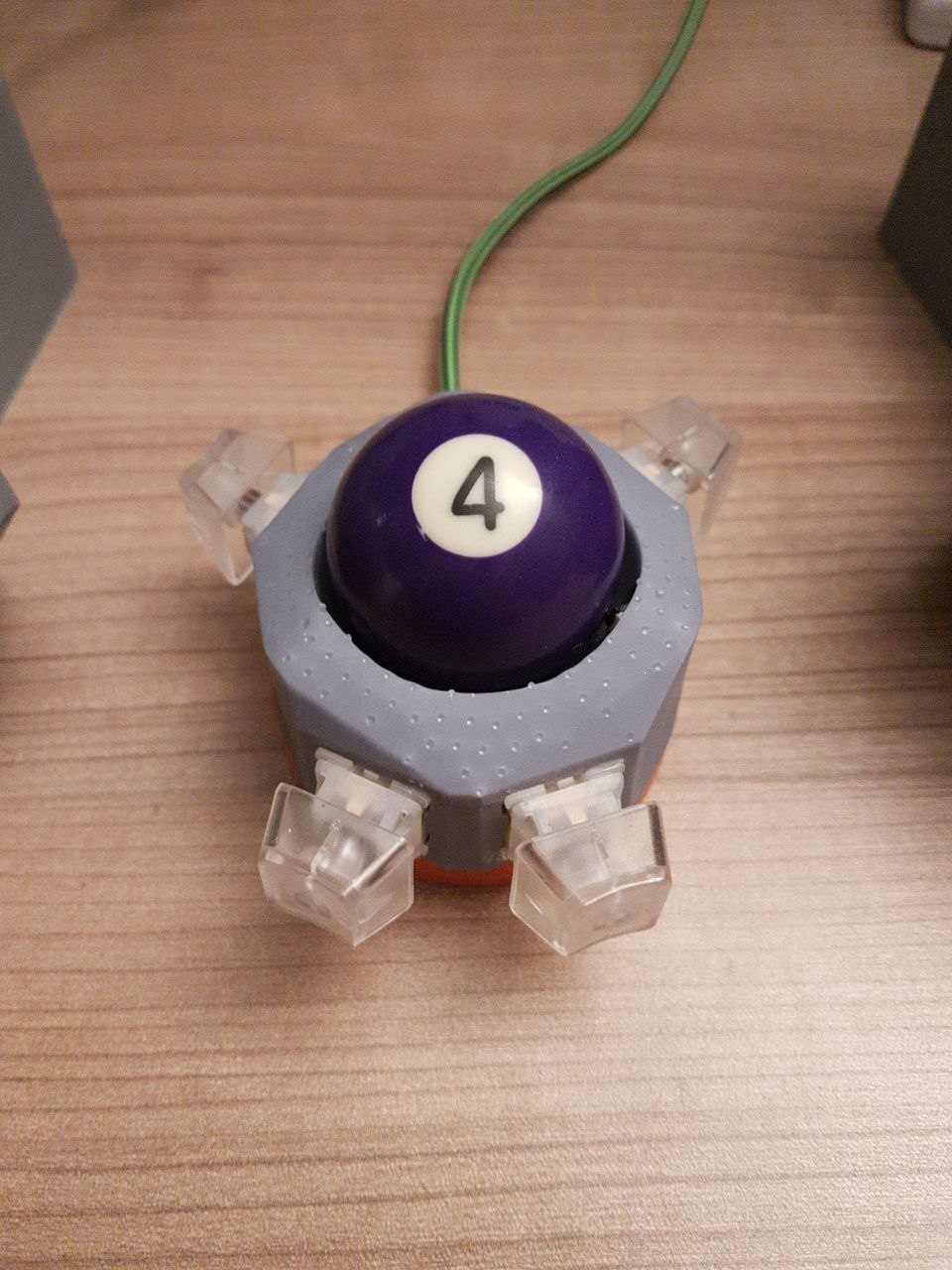
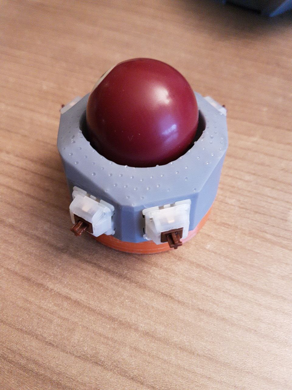
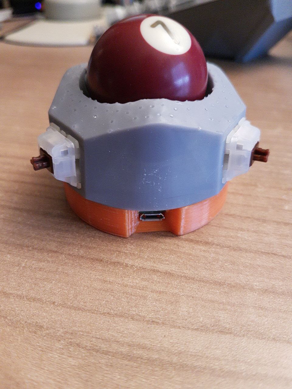
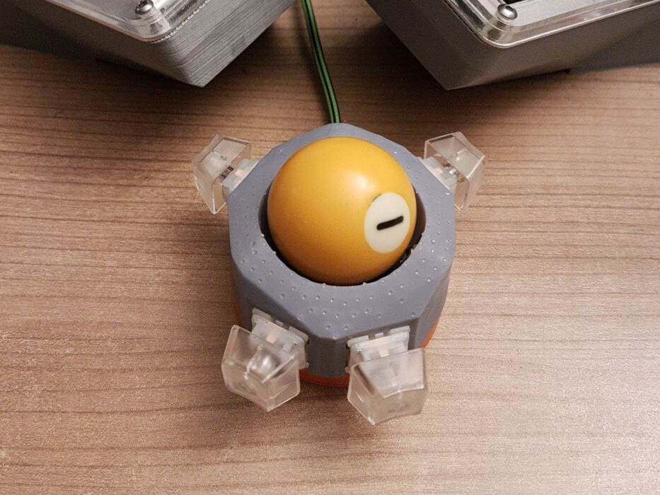
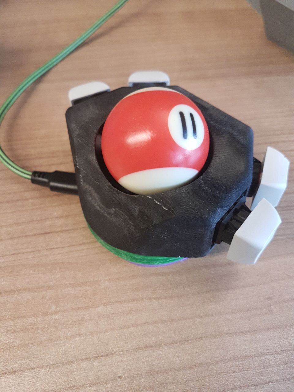
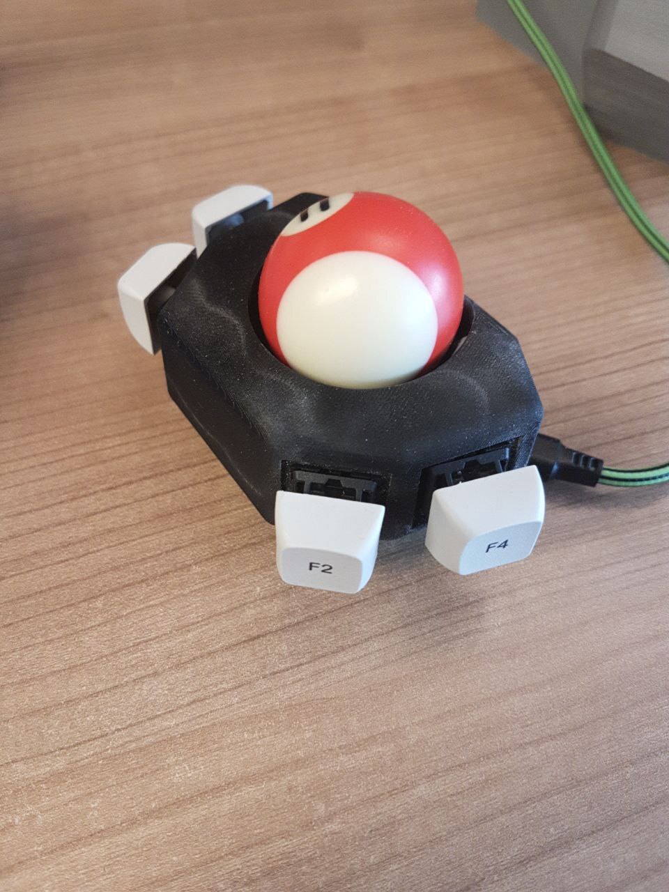
And there we go, a finished and working trackball.
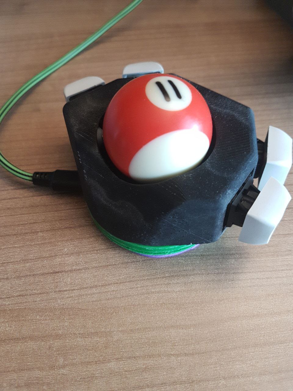
Improvements
For the second iteration we didn't do that many changes in the 3D design. The button orientation has been overhauled. This time we sat down and actually tried to find good positions using measurements on our hands. Also the Pi Pico is no longer mounted in the bottom shell, therefore removing the need of long cables to be able to disassemble the device.
This time I printed the top case on my recently acquired Sparkmaker SLA printer, with Anycubic ABS-like Resin black.
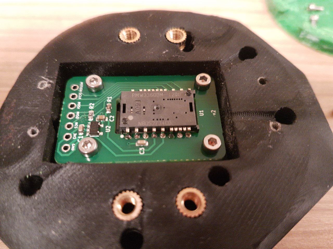
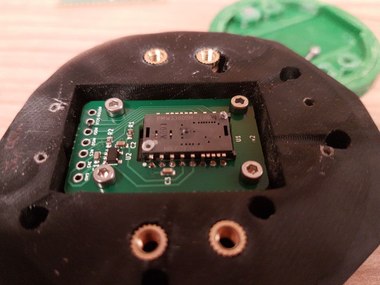
One useful aspect of the PMW3360 lens assembly are the two mounting posts. They can be heated to firmly keep them in place.
Recommendation: The lens can be permanently secured to the chip package by melting the lens’ guide posts over the chip with heat staking process. Please refer to the application note PMS0122‐LM19‐LSI‐AN for more details.
Instead of the official (confidential 🙄) method I recommend simply heating a screw or other piece of metal for 5 seconds with a lighter, then pressing it lightly on the post. Make sure everything is clean and the kapton tape removed between sensor and lens. You can see the before and after in the pictures below.
Apart from that nothing much has changed. The heat melt inserts are still super-glued in place.
And I used the same rubber mat for the underside. It works good enough that I didn't yet bother with a replacement.
User Experience
I have been using these Trackballs for about six weeks at the time of this writing. From a software and electronics perspective they work absolutely fine. No disconnects, jumping cursor or any strange behaviour was observable. So I'm very happy with that.
Ufortunately using them is also quite literally painful. They don't score high in terms of ergonomics, at all. The second version, with some more thought put into the placement and orientation of the switches, is an improvement, but there's still a long way to go.
But using a device each day that I've built completely myself, from the grounds up in pretty much all aspects, brings me a lot of joy. I highly recommend it.
License
The Trackball is licensed under the GNU General Public License.
This program is free software: you can redistribute it and/or modify
it under the terms of the GNU General Public License as published by
the Free Software Foundation, either version 3 of the License, or
(at your option) any later version.

This program is distributed in the hope that it will be useful,
but WITHOUT ANY WARRANTY; without even the implied warranty of
MERCHANTABILITY or FITNESS FOR A PARTICULAR PURPOSE.  See the
GNU General Public License for more details.

See <http://www.gnu.org/licenses/>.
More Pictures