Laser Engraver
Marlin based CNC laser engraver / cutter with 3D printed parts
Project published on November 25, 2022.Last updated on January 02, 2023.
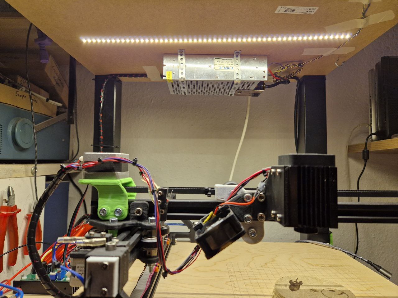
After dabbling in 3D printing for a couple of years now, I had to level-up my Makers toolkit. The next logical step, in my opinion, is laser engraving / laser cutting. I have to admit I was initially a bit scared and still have some respect for the potential hazards posed by the strong, focussed laser beam. So I decided to go slow and start with a low powered 2.5W diode laser.
⚠️ Be sure to always use proper laser safety goggles when working with such machines! ⚠️
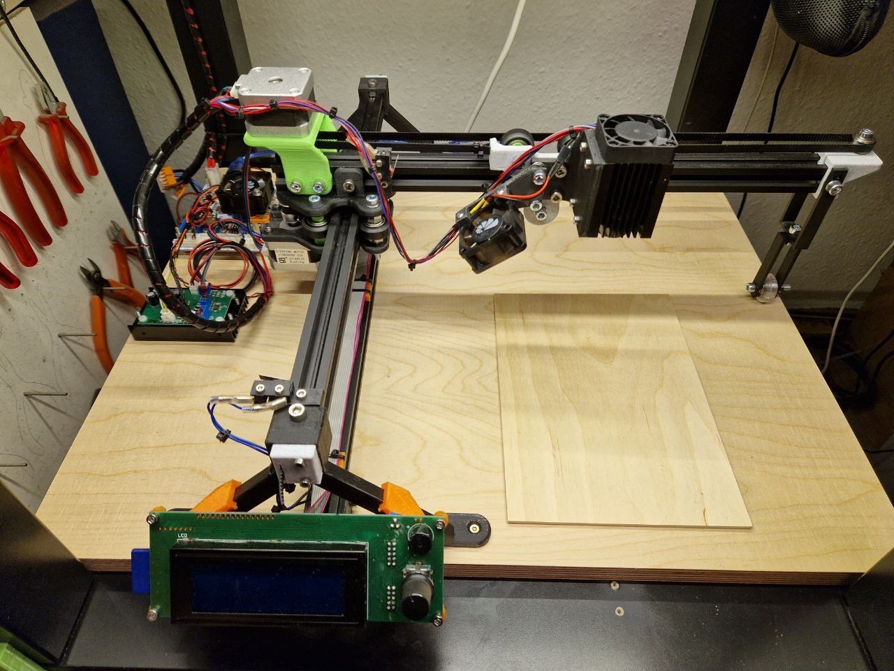
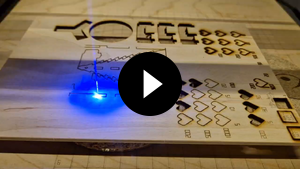
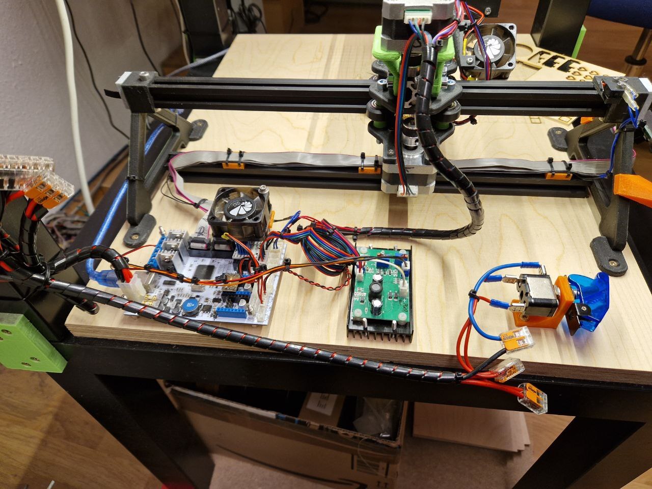
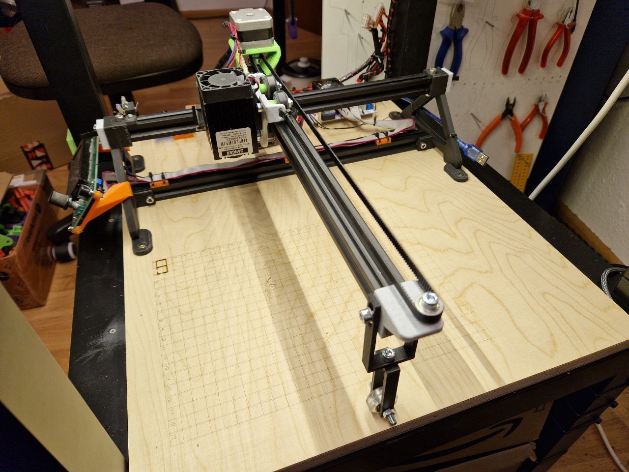
Table Of Contents
Hardware
I know I say this in a lot of articles here, probably in an attempt to justify my hoarding of electronic parts. 😳 But this was even better than most of my previous projects, in the sense that I didn't have to buy any parts at all, except for the 2500mW 450nm laser diode, which I got used from my colleague Philipp for just 13€. The rails I bought many years ago and never used. The steppers, mainboard, display, fans and cables came from my now disassembled CTC i3. Everything else came out of my parts bin.
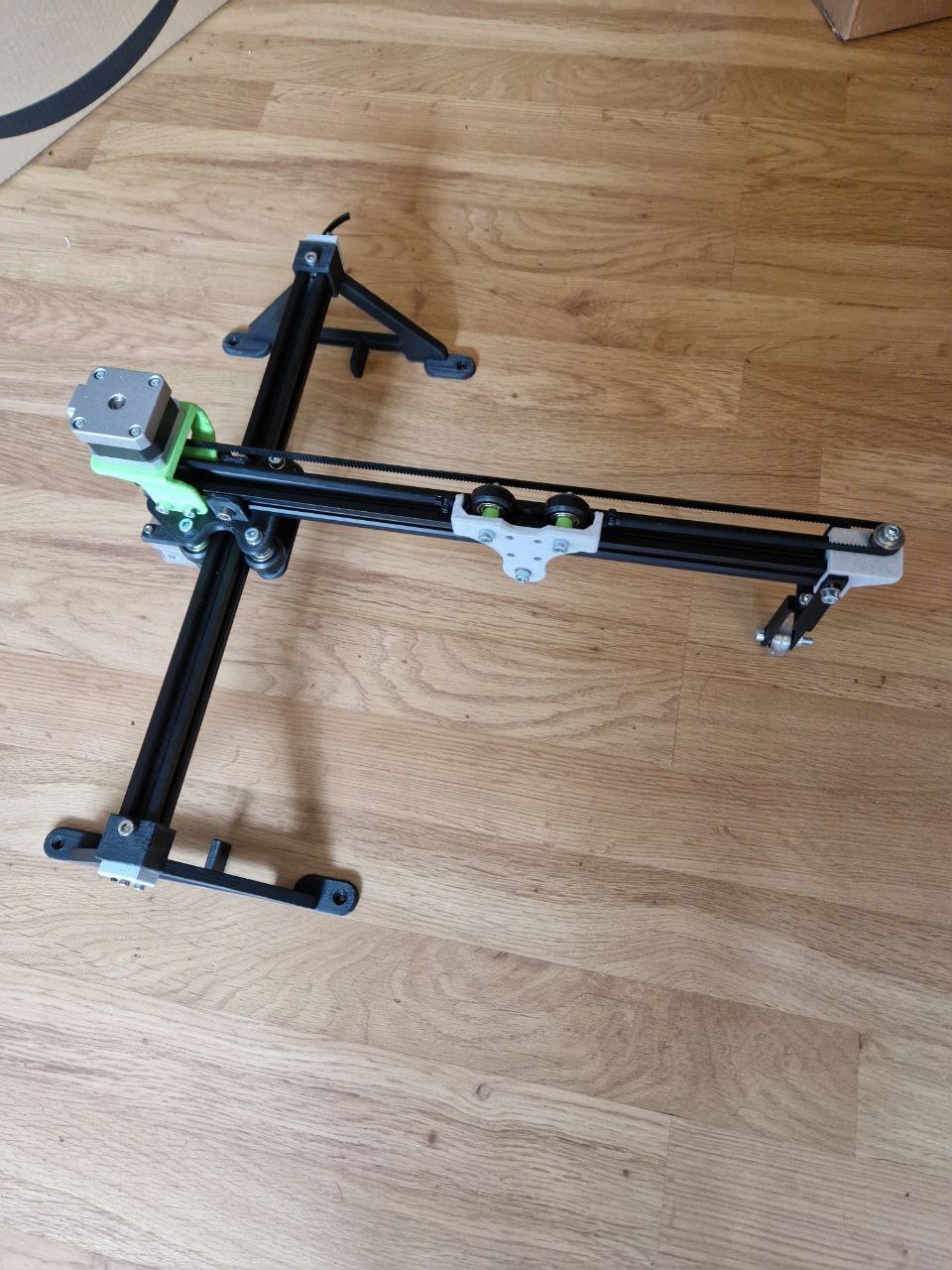
Mechanics
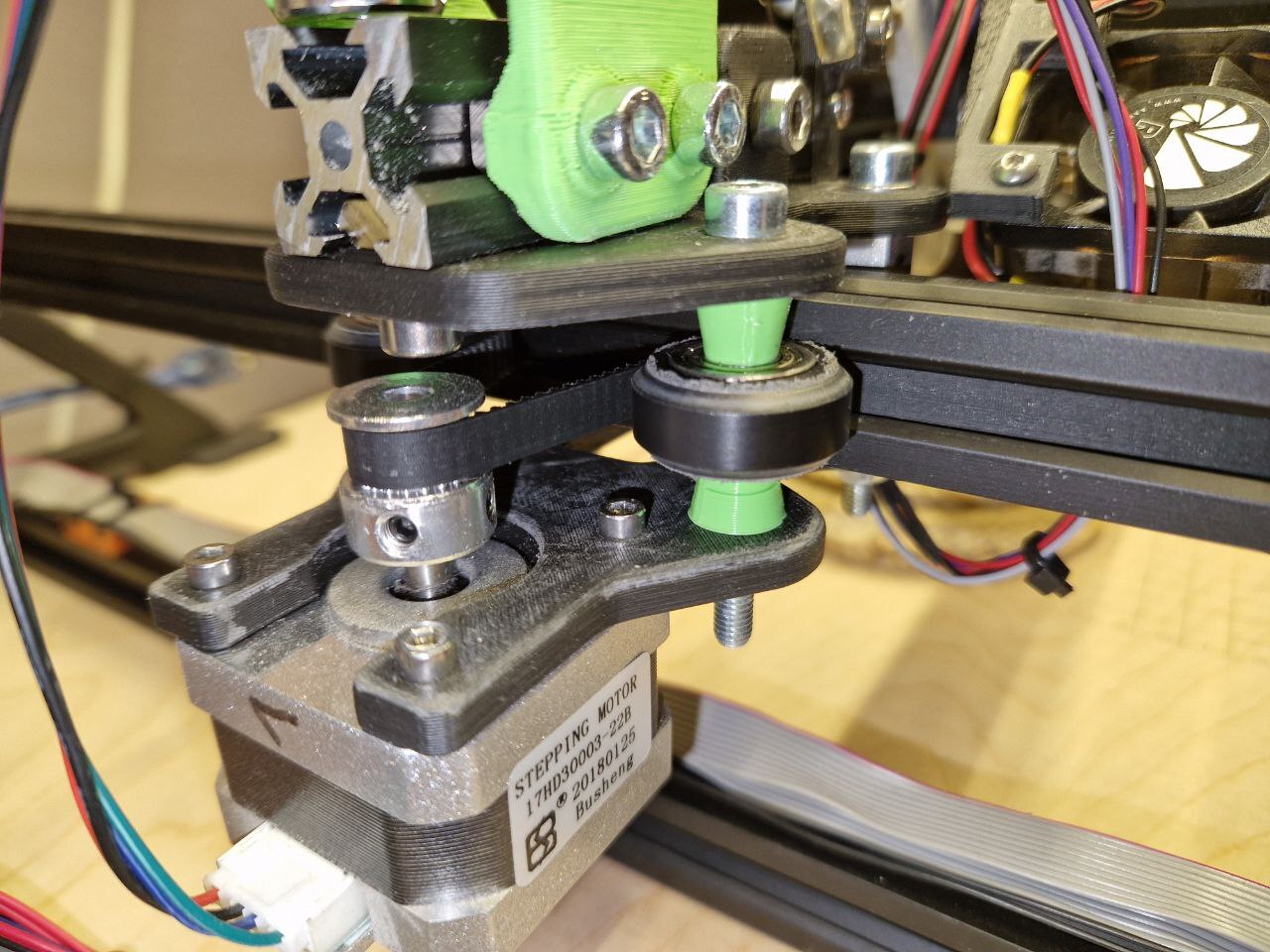
The mechanism is based on the "Cantilever Laser Engraver" by Meatball. This in turn is based on the "Cantilever Laser Engraver" by GeoDave. It uses 2020 aluminium extrusions with V-slot wheels for the X and Y axis.
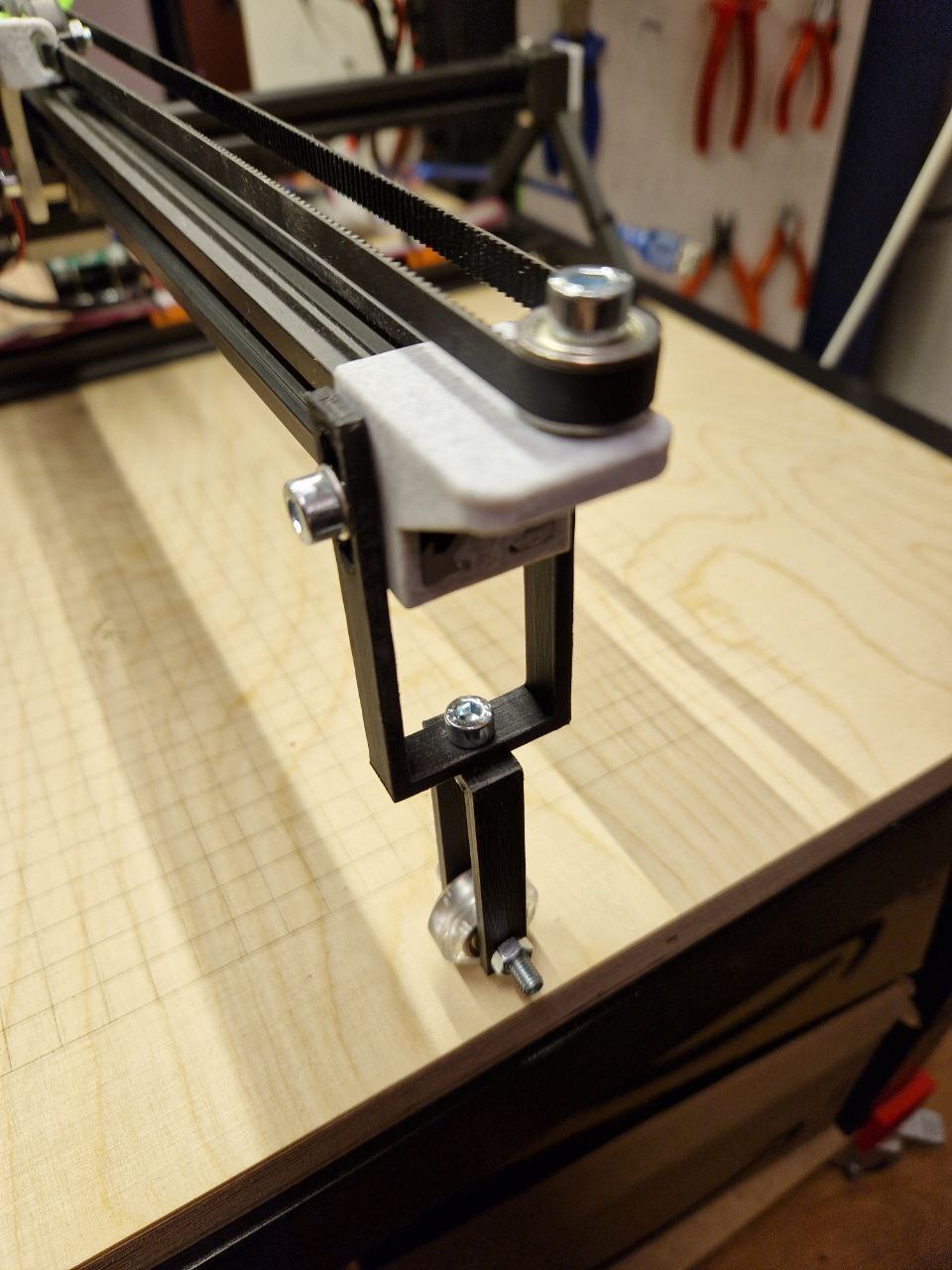
I really like this simple design that does not require a lot of parts. It has some problems with twisting of the Y-rail due to the weight hanging from the cantilever arm, but this can easily be solved by supporting the free-hanging side of the X-rail. Otherwise the length of the axes can be customized freely.
I had to do some modifications to the design files provided by Meatball.
The "Y-Axis Gantry Upper" has enlargened the holes for two of the four wheels, to be able to fit eccentric nuts that provide the required tensioning on the wheels. The "Y-Axis Gantry Lower" however has normal sized holes. So when using these parts, the two wheels are not actually moved perpendicular towards the extrusion, but are instead angled sideways. To avoid this problem I made the two holes in the lower bigger as well and used four instead of two eccentric nuts. I also slightly increased the distance between the two sets of wheels on the Y-axis, because it was very hard to fit the rail, even with the eccentric nuts as loose as possible.
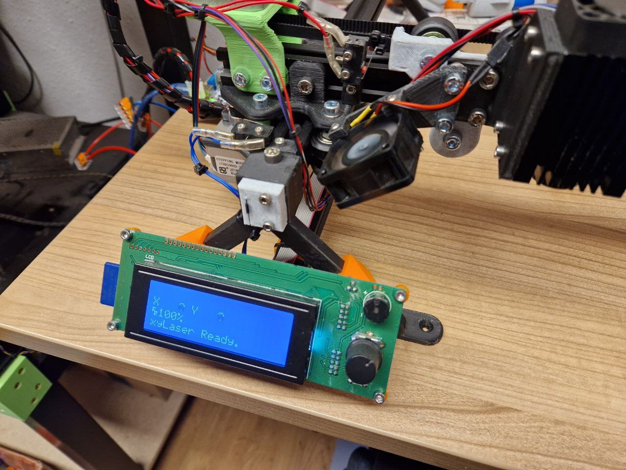
I also designed custom endstop mounts using M2.5 heat-melt inserts, as well as a support wheel for the free-hanging side of the cantilever arm and a mount for the Ultimaker Controller 2004 LCD.
The OpenSCAD and STL files for these parts can be found on my Printables profile.
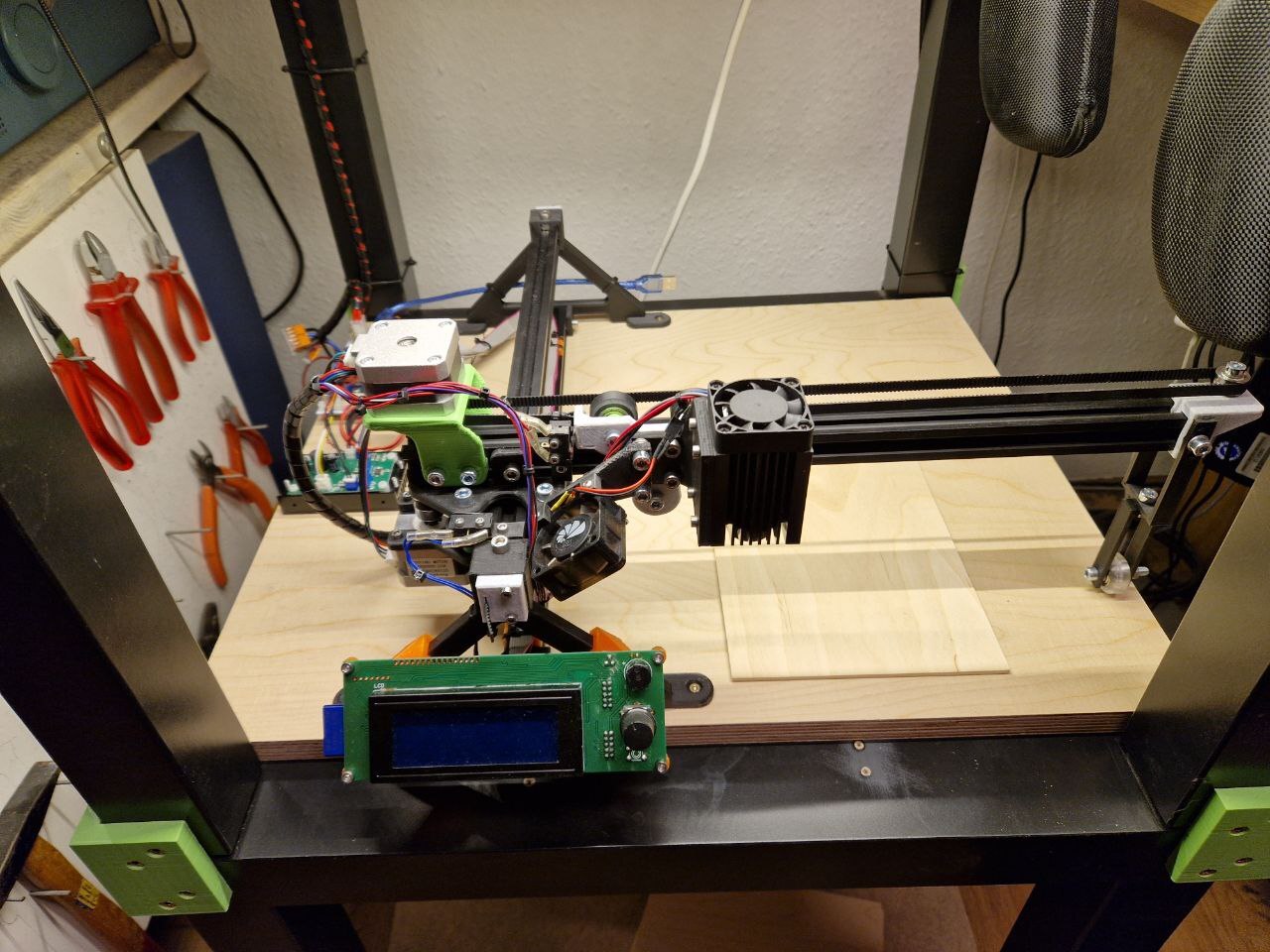
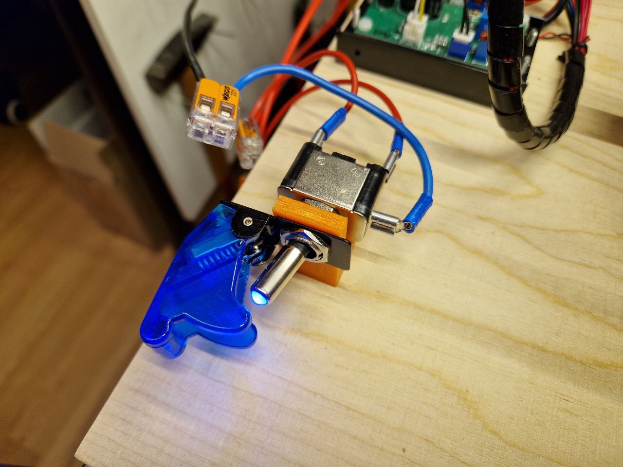
To fit the whole machine comfortably inside my Ikea Lack tower I mounted it on a 18mm mutliplex base plate with 540x440mm. The 3D printed feet of the Y-axis already have holes for countersunk screws, so I simply used wood screws there. To mount the mainboard PCB and laser heatsink I made 3.2mm holes for M3 screws and M3 stand-offs, drilling with a 6mm drill from the bottom to approximately half the depth of the base plate, so even cylindrical screw heads don't stand out from below the plate. I also added a power switch with a simple 3D printed mount.
Electronics
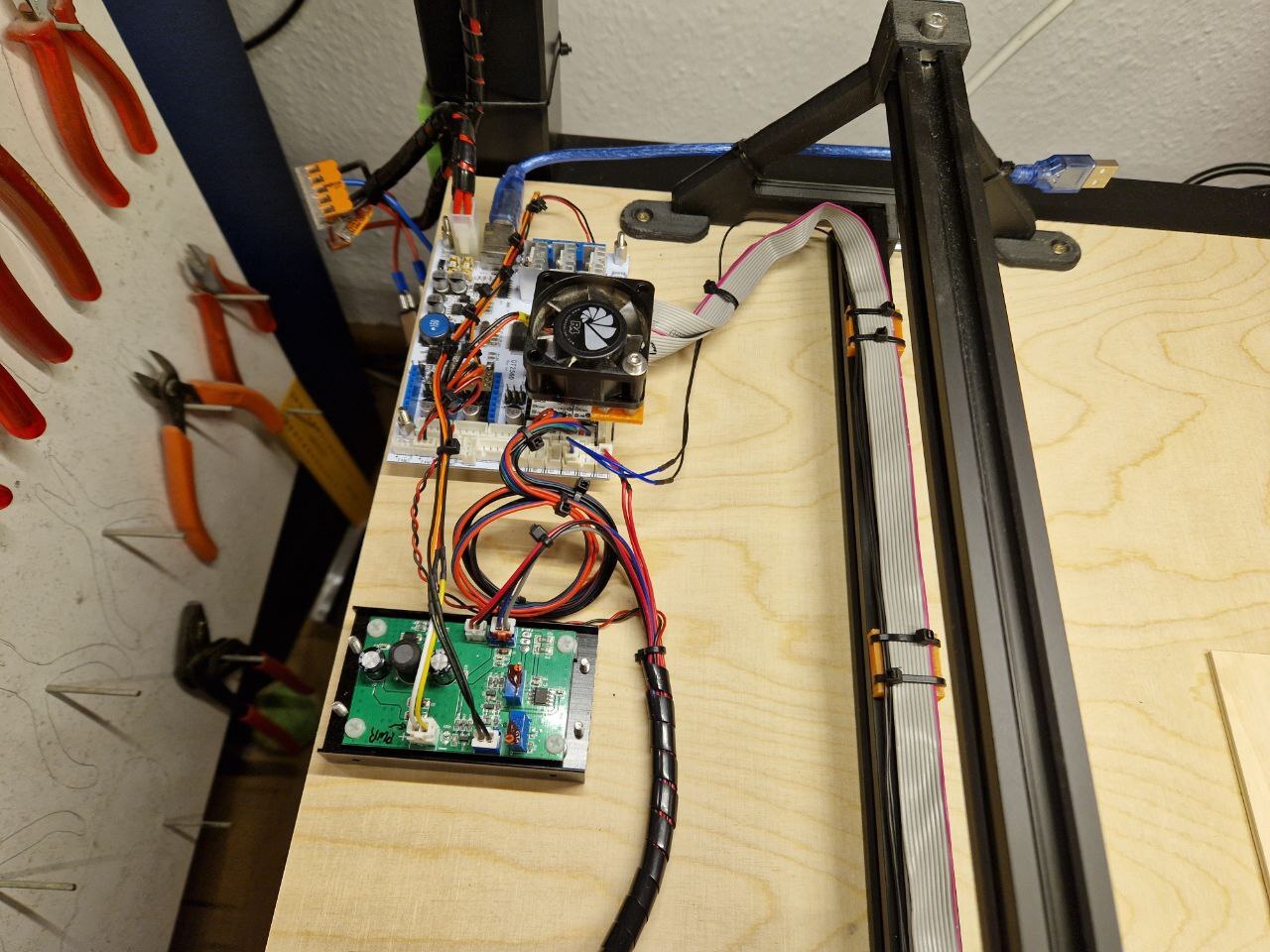
As mentioned above I used the electronics, namely mainboard, LCD and fans, from my old 3D printer.
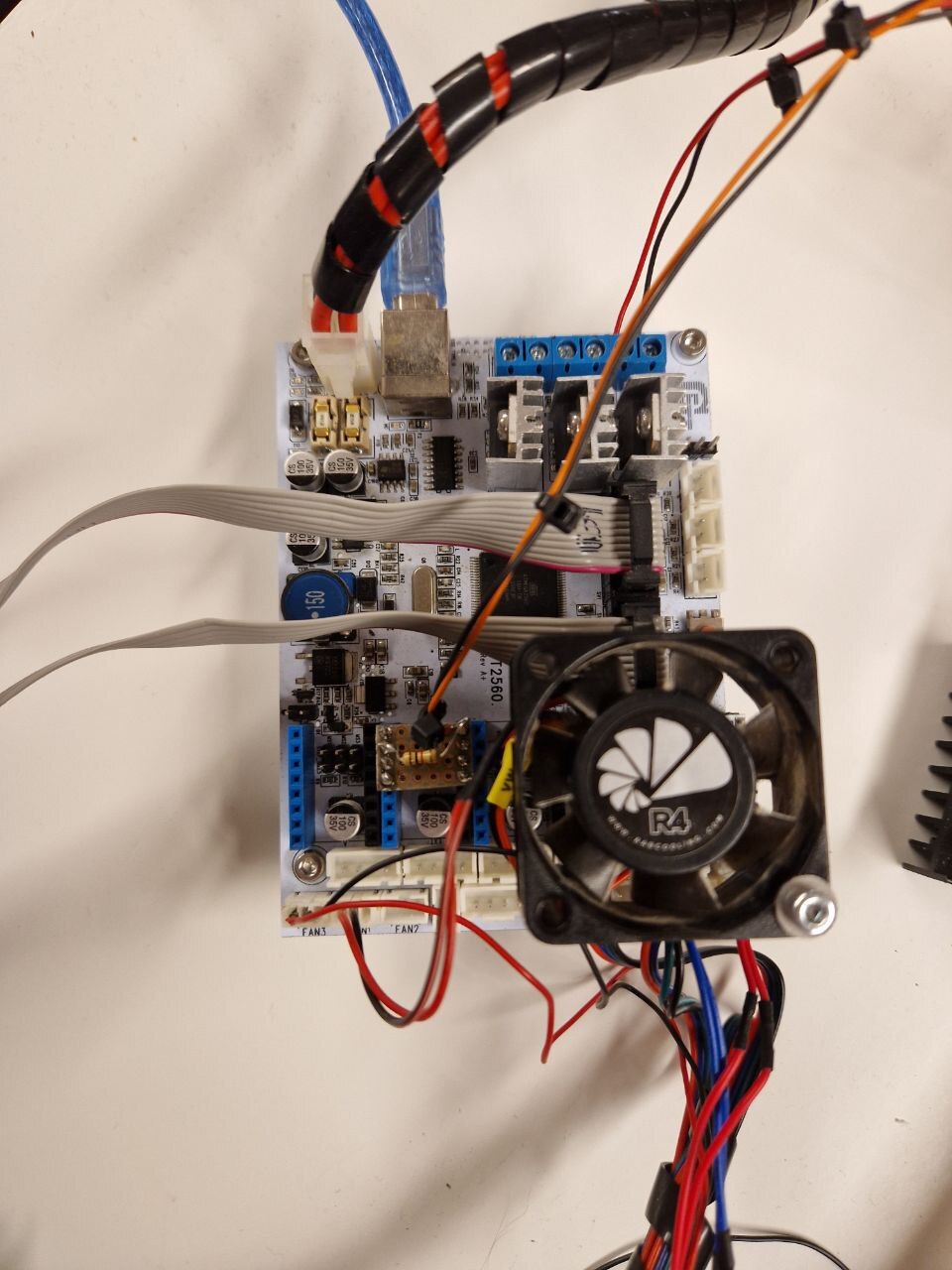
To connect the laser diode TTL input, a PWM capable pin from the microcontroller is required. To find one, we need to take a look at the schematics for the GT2560 mainboard, which can be found in the Geeetech Forums.
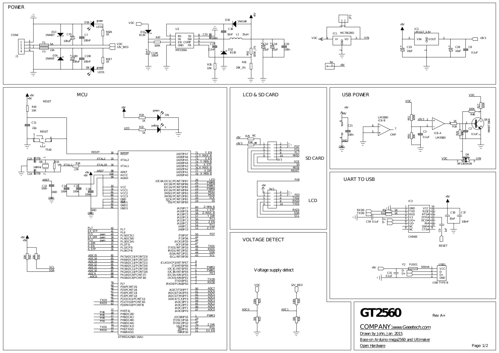
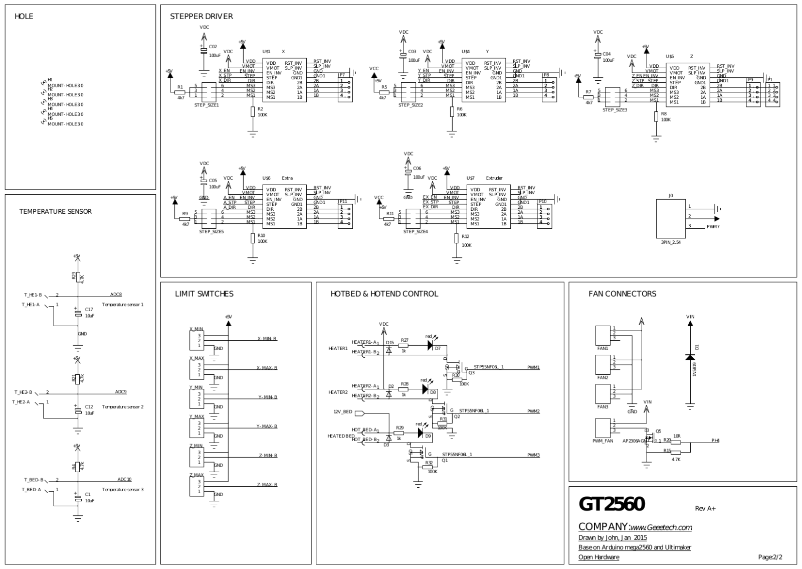
I decided to use PL4, the DIR pin of one of the now unused stepper drivers.
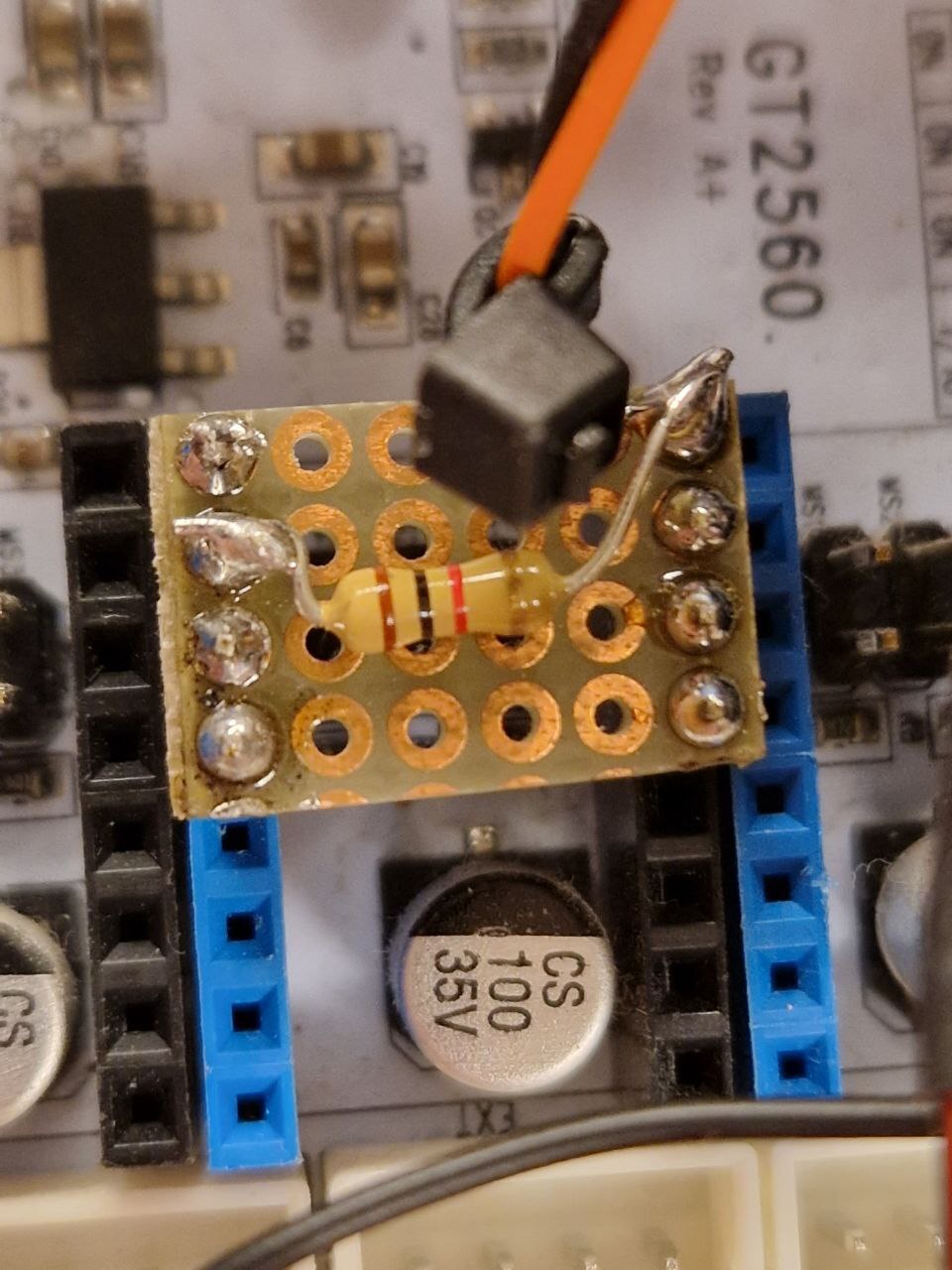
To connect to it I prepared a little piece of perfboard, to be placed in the slots like a stepstick, with an additional pull-up resistor to the 5V logic voltage present on the same header.
To find the pin number for the Marlin configuration, we can take a look at the Arduino Mega pin mappings, which show PL4 to be Arduino pin 45.
I'm not only connecting the laser TTL input to the mainboard, I'm also switching the 12V supply as well, by using the MOSFET originally intended for the hotend heater. This brought a little problem however. Both connectors of the laser PCB have a ground connection. And the ground connection is also the one that's switched, when connecting the laser to the power supply. So even when the MOSFET was turned off the laser still had a ground connection and was powered through the ground pin of the TTL connector, so it could never fully turn off. So if you do the same, make sure to only connect one of the two ground pins!
The power supply is simply reused from my Fabrikator Mini, it already was placed in the Ikea Lack tower. To save some space I now mounted it to the top of the next Lack table above the laser, with some strips of perforated metal sheet. Of course this is kind of problematic, as the rest of the machine is kind of designed to be easily transportable. I will have to find some kind of small alternative power supply.
Software
There's a surprisingly large amount of software involved in this project. All just to move a lamp around a bit 💡🤔
MCU Firmware
Most DIY laser engravers or CNC machines seem to use the GRBL firmware. Unfortunately this firmware only runs on Atmega328p MCUs, so I can not use it with the Atmega2560 on the GT2560 mainboard. There are some GRBL ports, for ESP32 or STM32 microcontrollers, but obviously these don't help either in my situation.
So I decided to use the trusty old Marlin Firmware, which was already running previously on my old 3D printers and this mainboard.
Configuring Marlin is pretty straight-forward, there's a configuration guide but the settings in the two config header files are well commented and pretty much self explanatory.
The only interesting parts are the laser-specific settings in Configuration_adv.h, like LASER_FEATURE and LASER_POWER_SYNC.
Apparently I seem to be the first person that tries to run an Ultimaker Controller 2004 LCD without a Z-Axis.
I had to add a couple of #ifdef Z_AXIS in src/lcd/HD44780/marlinui_HD44780.cpp.
You can see all the modifications to the configuration I initially made to get the machine running in this commit.
I also did some small changes to show the current laser power on the LCD status screen.
These changes can be seen in this commit.
I also opened a pull request to upstream them, which was merged into bugfix-2.1.x in November 2022.
Later I learned that Marlin does not allow setting home offsets further than 20mm away from endstops.
So I also added a custom menu command that simply executes G92 X0 Y0 to set the current position to zero.
Using this I can generate G-Code where the object to cut starts at coordinates (0, 0) while being able to position it arbitrarily on the machine itself.
My current Marlin configuration for the laser engraver can be found in the Git repo.
Host Software
Besides the microcontroller firmware, we also need some host software to prepare the G-Code from whatever kind of input file we start out with. There are two basic approaches for generating paths for the laser engraver. One is "rasterization", where a bitmap image is turned into commands line-by-line, enabling and disabling the laser at different parts of each line. This will draw an image similar to how a CRT TV works, which is useful eg. for engraving logos.
The other variant is "vectorization", where either a bitmap is converted to a vector path, or we start out with a vector file format, like svg. The laser can then follow the outline and optionally also fill between the outlines in some kind of pattern. This can then be used to cut shapes from objects.
At this point I should also mention Lightburn. This software is used both for the Laser cutters at Toolbox Bodensee, as well as by my neighbour, who uses it with an Ortur Laser Master 2. So I had some contact with it, and I have to admit, it works well and has a lot of functionality. But it is commercial paid software, not under any free software license, so it is not an option for me.
Below I will try to document all different free software packages I tried for laser engraving.
LaserGRBL
The first solution I found out about is LaserGRBL. It is a Windows-only program, but at least it is open-source / free software. As the name implies however, it is intended for use with the GRBL firmware.
The G-Code flavor of GRBL is considerably different compared to Marlin, but I was able to get it to work mostly.
For rasterization of bitmap images, GRBL produces G-Code with the laser power levels put inline with the movement commands.
G0 X25 Y10 S0
G1 X26.5 S150
G0 X28.25 Y10.25 S0
G1 X23 S150
Without further modifications, this only moves the toolhead, while keeping the laser off at all times, because Marlin by default does not process the power-level parts of the G-Code lines.
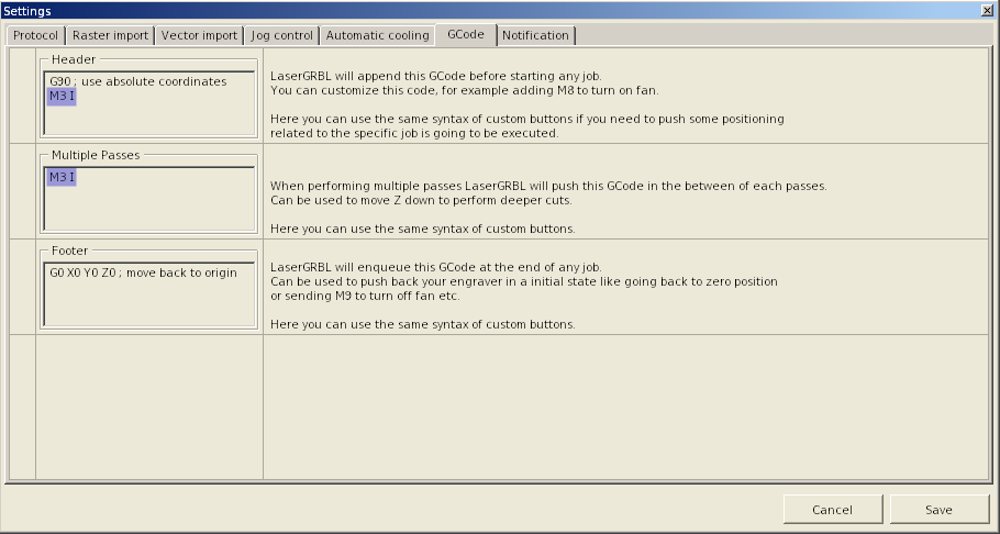
To get this to work, the "continuous inline power mode" has to be enabled by putting M3 I in the G-Code header setting of LaserGRBL, as well as at the end of the "Multiple Passes" G-Code section.
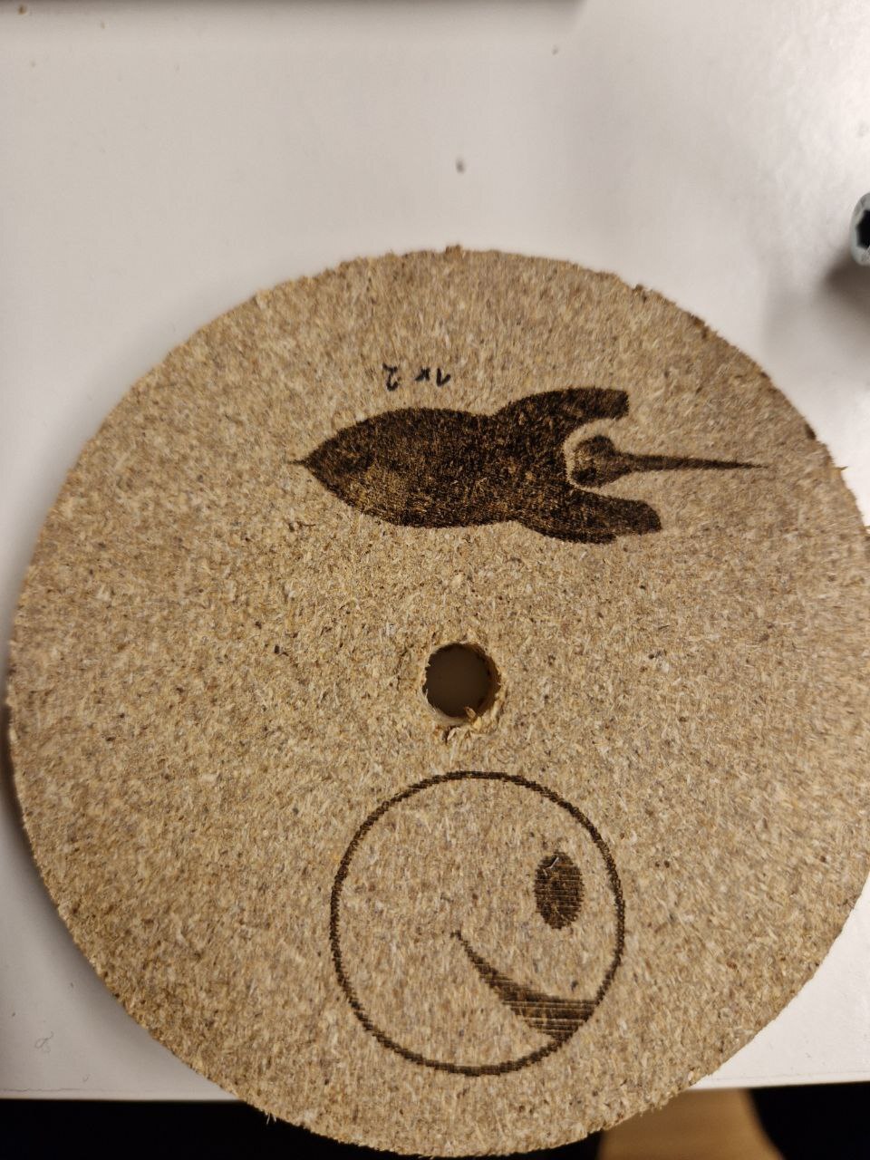
Here are the results of my first attempts of engraving a rasterized image into a piece of scrap wood. The rocket used 6 lines/mm, with default speed and a PWM range of 0-255. The smirkey used 4 lines/mm, with default speed and a PWM range of 0-150.
When trying to engrave vectorized paths, like the outline of an image, LaserGRBL produces different output, however. The power levels are now put on their own lines, but without any G-Code command, as usual shorthand used by GRBL.
S0
G0 X14.382 Y14.618
S150
G1 X14.618 Y14.382
S0
G0 X14.618 Y14.618
S150
G1 X14.457 Y14.457
Using a simple Python script, we can convert to the same format as used for rasterization. It simply reads the input file into the output file, skipping every line starting with an uppercase letter 'S', instead appending that to the next line.
I also noticed the speed set in LaserGRBL did not properly apply in Marlin. This is because, in vector mode, it puts a single "Fxxx" line at the beginning. Even though Marlin can interpret this in our configuration, there is no G1 mode set before, so Marlin does not know where to apply the speed. So I am also handling this case in the script as well. For raster input, LaserGRBL only puts the speed in a single G0 move at the beginning. So the speed does not apply to the G1 moves afterwards. This case is not handled yet.
In another vector job, I saw LaserGRBL generate output like the following.
G0X3Y2
S255
G1Y5F200
X0.7
Y8.347
X8.25
X8.75Y8.847
Y12.347
This is the very compact GRBL G-Code dialect, which leaves out spaces and also the modes, as long as they don't change. So to handle that, I remember the last G0/G1 mode, prepending it as needed to lines, while also adding the missing spaces for better human readable output.
As you can tell there are many different output formats from LaserGRBL and I'm not able to tell when it will generate what. But my script below should work for all variants I have seen up to now.
#!/usr/bin/env python

import sys

def add_spaces(s):
    prev = ' '
    r = ""
    for c in s:
        if str(prev).isdigit() and str(c).isalpha():
            r = r + " "
        r = r + c
        prev = c
    return r

def convert_gcode(fi, fo):
    power = ""
    speed = ""
    mode_g0 = True

    for line in fi:
        if line.startswith("S"):
            power = " " + line.rstrip()
        elif line.startswith("F"):
            speed = " " + line.rstrip()
        elif line.startswith("M3 S0"):
            fo.write(line)
            fo.write("G0 X0 Y0 S0 F1000\n")
            fo.write("G1 X1 Y0 S1 F1000\n")
            fo.write("G0 X0 Y0 S0 F1000\n")
            fo.write("G1 X0 Y1 S1 F1000\n")
            fo.write("G0 X0 Y0 S0 F1000\n")
        else:
            s = add_spaces(line.rstrip())
            if line.startswith("G1"):
                mode_g0 = False
                s += power
                s += speed
            elif line.startswith("G0"):
                mode_g0 = True
                s += power
                if (power != " S0") and (power != ""):
                    print("Warning: G0 move with power not zero!" + power)
            elif line.startswith("X") or line.startswith("Y"):
                if mode_g0:
                    s = "G0 " + s
                    s += power
                    if (power != " S0") and (power != ""):
                        print("Warning: G0 move with power not zero!" + power)
                else:
                    s = "G1 " + s
                    s += power
                    s += speed
            s += "\n"
            fo.write(s)

def main():
    if len(sys.argv) < 3:
        print("Usage:")
        print("    " + sys.argv[0] + " input.nc output.gcode")
        sys.exit(1)

    in_file = sys.argv[1]
    out_file = sys.argv[2]

    with open(in_file, 'r') as fi, open(out_file, 'w') as fo:
        convert_gcode(fi, fo)

if __name__ == '__main__':
    main()
You can also find this script in the Git repo.
Here is my first attempt of cutting a vector outline of an image out of a piece of paper. I used Marlins default speed and a PWM setting of 150 out of 255.

For these tests I have simply used LaserGRBL to produce a G-Code file, which I have then transferred to an SD card for direct use in the engraver. LaserGRBL also can directly connect to the machine via the serial port. This has worked for me for a bit, but even though you can set the G-Code flavor to Marlin in the LaserGRBL settings, it does not really work properly. You can jog the toolhead but homing is not possible. I also had to reduce the polling frequency in the LaserGRBL settings to 'Quiet' and disable Soft-Reset to get it to work inside the VirtualBox VM I used at first to run the program.
It is also possible to run LaserGRBL in Wine / with PlayOnLinux. At first I was not able to run this PlayOnLinux script due to Winetricks downloads failing with invalid checksums. But after trying a couple of days later, with the exact same script, the installation worked fine. I had to make the same changes to the settings as described for VirtualBox above. Unfortunately in Wine LaserGRBL hangs when attempting to load rasterized images. So I went back to the VM for that.
Also for all the above tests with LaserGRBL I have imported raster bitmap images and either rastered them, or vectorized them within LaserGRBLs UI.
With bitmaps it is possible to position the resulting G-Code paths with an offset from the zero position of the machine.
This is not possible when using LaserGRBL to import SVG vector paths.
With them, the output will always start at coordinates (0, 0).
You will then have to set the proper offset on the machine itself, as described in the Marlin section above.
Inkscape
Inkscape includes the G-Code Tools Plugin from the russian-language CNC-Club forums. Unfortunately I was not able to find much up-to-date english-language documentation for this. It is also relatively complicated and unintuitive.
I was able to get it to generate G-Code from a path, but not with any laser power instructions yet. This section will be updated if I have more success in the future. Until then I'm just using Inkscape to export svg files for LaserGRBL.
FreeCAD
FreeCAD has the Path Workbench, which can be used to create G-Code instructions for all kinds of CNC machines. It is not really complete and fool-proof yet, unfortunately. And it is also not designed for pure 2D machines, like laser engravers, by default.
I have not yet tested that.
Working with G-Code
One nice feature I saw in LaserGRBL, but was not able to use with Marlin, is the ability to draw the outline of the object to be cut, for positioning of the stock material. So I quickly made up a small Python script that analyzes a G-Code file, taking the coordinates from all G1 cutting moves and generating their bounding box, which is then drawn on the lowest possible power setting multiple times. I copy this file to the SD card, start it, and just abort it when I'm done with the preparations.
#!/usr/bin/env python

import sys

pwr = 1
iterations = 100
speed = 3000

def file_bounding_box(f):
    x_min = None
    x_max = None
    y_min = None
    y_max = None
    mode_g1 = False

    for line in f:
        if line.startswith("G1"):
            mode_g1 = True
        elif line.startswith("G0"):
            mode_g1 = False

        if mode_g1:
            x_pos = line.find("X")
            if x_pos > -1:
                x_str = line[x_pos + 1:]
                x_num = float(x_str.split()[0])
                #print("found x: " + str(x_num))
                if (x_min == None) or (x_num < x_min):
                    x_min = x_num
                if (x_max == None) or (x_num > x_max):
                    x_max = x_num

            y_pos = line.find("Y")
            if y_pos > -1:
                y_str = line[y_pos + 1:]
                y_num = float(y_str.split()[0])
                #print("found y: " + str(y_num))
                if (y_min == None) or (y_num < y_min):
                    y_min = y_num
                if (y_max == None) or (y_num > y_max):
                    y_max = y_num

    return ( x_min, x_max, y_min, y_max )

def write_outline(f, bb):
    def write(s):
        #print(s)
        f.write(s + "\n")

    x_min, x_max, y_min, y_max = bb

    print("x_min: " + str(x_min))
    print("x_max: " + str(x_max))
    print("y_min: " + str(y_min))
    print("y_max: " + str(y_max))

    pos = [
        ( x_min, y_min ),
        ( x_max, y_min ),
        ( x_max, y_max ),
        ( x_min, y_max ),
    ]

    # header
    write("G90")
    write("G28")
    write("G92 X0 Y-20")
    write("M3 I")
    write("M3 S0")

    write("G0 X0 Y0 S0 F" + str(speed))
    write("G1 X1 Y0 S1 F" + str(speed))
    write("G0 X0 Y0 S0 F" + str(speed))
    write("G1 X0 Y1 S1 F" + str(speed))
    write("G0 X0 Y0 S0 F" + str(speed))

    write("G0 X" + str(x_min) + " Y" + str(y_min) + " S0 F" + str(speed))

    for i in range(0, iterations):
        for x, y in pos:
            write("G1 X" + str(x) + " Y" + str(y) + " S" + str(pwr) + " F" + str(speed))

    write("M5")
    write("G0 X" + str(x_min) + " Y" + str(y_min) + " S0 F" + str(speed))

def main():
    if len(sys.argv) < 3:
        print("Usage:")
        print("    " + sys.argv[0] + " input.nc output.gcode")
        sys.exit(1)

    in_file = sys.argv[1]
    out_file = sys.argv[2]

    with open(in_file, 'r') as f:
        bb = file_bounding_box(f)

    with open(out_file, 'w') as f:
        write_outline(f, bb)

if __name__ == '__main__':
    main()
You can also find this script in the Git repo.
I also did some experimentation with programatically generating G-Code myself, using a simple Python script as well. It's drawing a grid for reference on the base plate of the machine, including numerical position indicators.
#!/usr/bin/env python

filename = "grid.gcode"
w = 200
h = 280
d = 10
pwr = 100
speed_g0 = 3000
speed_g1 = 1000

digits = [
    [
        # 0
        (0.0, 0.0),
        (0.0, 1.0),
        (1.0, 1.0),
        (1.0, 0.0),
        (0.0, 0.0)
    ], [
        # 1
        (0.5, 0.0),
        (0.5, 1.0)
    ], [
        # 2
        (0.0, 1.0),
        (1.0, 1.0),
        (1.0, 0.5),
        (0.0, 0.5),
        (0.0, 0.0),
        (1.0, 0.0),
    ], [
        # 3
        (0.0, 1.0),
        (1.0, 1.0),
        (1.0, 0.5),
        (0.0, 0.5),
        (1.0, 0.5),
        (1.0, 0.0),
        (0.0, 0.0),
    ], [
        # 4
        (0.0, 1.0),
        (0.0, 0.5),
        (1.0, 0.5),
        (1.0, 1.0),
        (1.0, 0.0),
    ], [
        # 5
        (1.0, 1.0),
        (0.0, 1.0),
        (0.0, 0.5),
        (1.0, 0.5),
        (1.0, 0.0),
        (0.0, 0.0),
    ], [
        # 6
        (1.0, 1.0),
        (0.0, 1.0),
        (0.0, 0.0),
        (1.0, 0.0),
        (1.0, 0.5),
        (0.0, 0.5),
    ], [
        # 7
        (0.0, 1.0),
        (1.0, 1.0),
        (1.0, 0.0),
    ], [
        # 8
        (1.0, 0.5),
        (1.0, 1.0),
        (0.0, 1.0),
        (0.0, 0.5),
        (1.0, 0.5),
        (1.0, 0.0),
        (0.0, 0.0),
        (0.0, 0.5),
    ], [
        # 9
        (1.0, 0.5),
        (1.0, 1.0),
        (0.0, 1.0),
        (0.0, 0.5),
        (1.0, 0.5),
        (1.0, 0.0),
        (0.0, 0.0),
    ]
]

font_w = 1.5
font_h = 3.0
font_d = 0.5

def draw_digit(f, i, sx, sy, ox, oy):
    dig = digits[i]
    n = 0
    for p in dig:
        x, y = p
        s = ""

        if n == 0:
            s += "G0 S0 F" + str(speed_g0)
        else:
            s += "G1 S" + str(pwr) + " F" + str(speed_g1)

        s += " X" + str(ox + sx * x)
        s += " Y" + str(oy + sy * y)

        print(s)
        f.write(s + "\n")
        n += 1

    return s

with open(filename, 'w') as f:
    def write(s):
        print(s)
        f.write(s + "\n")

    # header
    write("G90")
    write("G28")
    write("G92 X0 Y-20")
    write("M3 I")
    write("M3 S0")
    write("")

    # first line is not having the power applied
    # so just draw it twice
    # TODO why?
    write("G0 X0 Y0 S0 F" + str(speed_g0))
    write("G1 X0 Y" + str(h) + " S" + str(pwr) + " F" + str(speed_g1))

    # vertical lines
    write("; vertical lines")
    for x in range(0, w + d, d):
        write("G0 X" + str(x) + " Y0 S0 F" + str(speed_g0))
        write("G1 X" + str(x) + " Y" + str(h) + " S" + str(pwr) + " F" + str(speed_g1))
    write("")

    # horizontal lines
    write("; horizontal lines")
    for y in range(0, h + d, d):
        write("G0 X0 Y" + str(y) + " S0 F" + str(speed_g0))
        write("G1 X" + str(w) + " Y" + str(y) + " S" + str(pwr) + " F" + str(speed_g1))
    write("")

    # horizontal text
    for x in range(0, w, d):
        n = int(x / 10)
        write("; number '" + str(n) + "' at x " + str(x))
        if n >= 10:
            draw_digit(f, int(n / 10), font_w, font_h, font_d + x, font_d)
            draw_digit(f, int(n % 10), font_w, font_h, 2 * font_d + font_w + x, font_d)
        else:
            draw_digit(f, n, font_w, font_h, font_d + x, font_d)
    write("")

    # vertical text
    for y in range(d, h, d):
        n = int(y / 10)
        write("; number '" + str(n) + "' at y " + str(y))
        if n >= 10:
            draw_digit(f, int(n / 10), font_w, font_h, font_d, font_d + y)
            draw_digit(f, int(n % 10), font_w, font_h, 2 * font_d + font_w, font_d + y)
        else:
            draw_digit(f, n, font_w, font_h, font_d, font_d + y)
    write("")

    # footer
    write("M5")
    write("G0 X0 Y0 F" + str(speed_g0))
You can also find this script in the Git repo.
I like the idea but unfortunately it has some problems in practice. When changing the focus level of my laser diode, it's very easy to also change the offset in the X and Y axes. So the grid is not properly aligned for long. But it still looks nice.
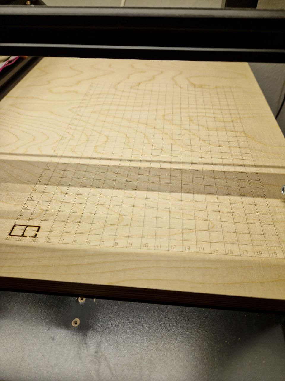
If you look closely, you can see the first run I did with a power setting of 50 / 255. This was not strong enough, the lines are only faintly visible. So I did another run with 100 / 255 over it. This was enough power for nice visible lines, but the laser offset unfortunately shifted slightly between the runs.
As I grew tired of removing, flashing and re-inserting of the SD card, I decided to also write a quick little G-Code sender for the serial port.
#!/usr/bin/env python

import sys
import serial

if len(sys.argv) < 3:
    print("Usage:")
    print("    " + sys.argv[0] + " /dev/serial/port input.gcode")
    sys.exit(1)

port_file = sys.argv[1]
in_file = sys.argv[2]

port = serial.Serial()
port.port = port_file
port.baudrate = 115200
#port.timeout = 0.0

max_cmd_buffer = 5
counter = 0

def connect_serial():
    try:
        port.open()
        if port.is_open:
            print("connected to: " + port_file)
        else:
            print("error connecting to " + port_file)
            sys.exit(1)
    except serial.serialutil.SerialException:
        print("error connecting to " + port_file)
        sys.exit(1)

def wait_for_text(s):
    while True:
        response = port.read_until().decode().strip()
        print("rx w: " + response)
        if response.startswith(s):
            break
        elif response.startswith("Error"):
            print(response)
            print("CNC returned error. aborting.")
            abort_print(False)
            port.close()
            sys.exit(1)

def abort_print(wait_for_oks = True):
    global counter

    print("tx: M5")
    port.write("M5\n".encode())
    counter += 1

    print("tx: G0 X0 Y0 F1000")
    port.write("G0 X0 Y0 F1000\n".encode())
    counter += 1

    if wait_for_oks:
        while counter > 0:
            wait_for_text("ok")
            counter -= 1

def send_file(f):
    global counter

    for line in f:
        if ";" in line:
            line = line.split(";")[0]

        line = line.strip()

        if len(line) <= 0:
            print("skipping empty line")
            continue

        print("tx: " + line)
        tx = line.encode() + b'\n'
        port.write(tx)

        counter += 1
        print("cnt=" + str(counter))

        while counter >= max_cmd_buffer:
            response = port.read_until().decode().strip()
            #print("rx: " + response)
            if response.startswith("ok"):
                counter -= 1
                print("cnt=" + str(counter))
            elif response.startswith("Error"):
                print(response)
                print("CNC returned error. aborting.")
                abort_print(False)
                port.close()
                sys.exit(1)

def main():
    connect_serial()

    print("waiting for CNC to reset")
    wait_for_text("start")

    print("auto-homing after reset")
    print("tx: G28")
    port.write("G28\n".encode())
    wait_for_text("ok")

    try:
        with open(in_file, 'r') as f:
            send_file(f)

        while counter > 0:
            wait_for_text("ok")
            counter -= 1

        print("workaround. kill when done.")
        while True:
            pass
    except KeyboardInterrupt:
        print("user interrupt. aborting.")
        abort_print(True)

    port.close()

if __name__ == '__main__':
    main()
You can also find this script in the Git repo.
Of course it's important to use the proper speed, power and number of iterations for each object to cut. Not enough power or iterations, or too high of a speed, and the object will still be part of the stock material. Too much power or iterations and not only the object will be cut, but also the base plate below.
So I first did some tests manually, which is relatively time consuming. I then made another Python script go generate G-Code for a cutting test, varying speed and number of iterations.
#!/usr/bin/env python

# general settings
filename = "cut_test.gcode"
pwr = 255
pwr_num = 150
speed_g0 = 3000
speed_g1_num = 500

# settings of single test shape
width = 10
height = 10
dist = 2

# range for tests
iterations = [ 5, 10, 15, 20 ]
speeds_g1 = [ 1000, 500, 200 ]

def drawSquare(w, h, x, y, speed_g1):
    write("G0 X" + str(x) + " Y" + str(y) + " S0 F" + str(speed_g0))
    square = [
        ( x + w, y ),
        ( x + w, y + h ),
        ( x, y + h ),
        ( x, y ),
    ]
    for xp, yp in square:
        write("G1 X" + str(xp) + " Y" + str(yp) + " S" + str(pwr) + " F" + str(speed_g1))

def drawHeart(w, h, x, y, speed_g1):
    heart = [
        ( 0.0, 5.0 / 8.0 ),
        ( 0.0, 6.0 / 8.0 ),
        ( 0.1, 7.0 / 8.0 ),
        ( 0.2, 8.0 / 8.0 ),
        ( 0.3, 8.0 / 8.0 ),
        ( 0.4, 7.0 / 8.0 ),
        ( 0.5, 6.0 / 8.0 ),
        ( 0.6, 7.0 / 8.0 ),
        ( 0.7, 8.0 / 8.0 ),
        ( 0.8, 8.0 / 8.0 ),
        ( 0.9, 7.0 / 8.0 ),
        ( 1.0, 6.0 / 8.0 ),
        ( 1.0, 5.0 / 8.0 ),
        ( 0.9, 4.0 / 8.0 ),
        ( 0.8, 3.0 / 8.0 ),
        ( 0.7, 2.0 / 8.0 ),
        ( 0.6, 1.0 / 8.0 ),
        ( 0.5, 0.0 / 8.0 ),
        ( 0.4, 1.0 / 8.0 ),
        ( 0.3, 2.0 / 8.0 ),
        ( 0.2, 3.0 / 8.0 ),
        ( 0.1, 4.0 / 8.0 ),
        ( 0.0, 5.0 / 8.0 )
    ]
    write("G0 X" + str(x + heart[0][0] * w) + " Y" + str(y + heart[0][1] * h) + " S0 F" + str(speed_g0))
    for xp, yp in heart:
        write("G1 X" + str(x + xp * w) + " Y" + str(y + yp * h) + " S" + str(pwr) + " F" + str(speed_g1))

def drawShape(w, h, x, y, speed_g1):
    #drawSquare(w, h, x, y, speed_g1)
    drawHeart(w, h, x, y, speed_g1)

digits = [
    [
        # 0
        (0.0, 0.0),
        (0.0, 1.0),
        (1.0, 1.0),
        (1.0, 0.0),
        (0.0, 0.0)
    ], [
        # 1
        (0.5, 0.0),
        (0.5, 1.0)
    ], [
        # 2
        (0.0, 1.0),
        (1.0, 1.0),
        (1.0, 0.5),
        (0.0, 0.5),
        (0.0, 0.0),
        (1.0, 0.0),
    ], [
        # 3
        (0.0, 1.0),
        (1.0, 1.0),
        (1.0, 0.5),
        (0.0, 0.5),
        (1.0, 0.5),
        (1.0, 0.0),
        (0.0, 0.0),
    ], [
        # 4
        (0.0, 1.0),
        (0.0, 0.5),
        (1.0, 0.5),
        (1.0, 1.0),
        (1.0, 0.0),
    ], [
        # 5
        (1.0, 1.0),
        (0.0, 1.0),
        (0.0, 0.5),
        (1.0, 0.5),
        (1.0, 0.0),
        (0.0, 0.0),
    ], [
        # 6
        (1.0, 1.0),
        (0.0, 1.0),
        (0.0, 0.0),
        (1.0, 0.0),
        (1.0, 0.5),
        (0.0, 0.5),
    ], [
        # 7
        (0.0, 1.0),
        (1.0, 1.0),
        (1.0, 0.0),
    ], [
        # 8
        (1.0, 0.5),
        (1.0, 1.0),
        (0.0, 1.0),
        (0.0, 0.5),
        (1.0, 0.5),
        (1.0, 0.0),
        (0.0, 0.0),
        (0.0, 0.5),
    ], [
        # 9
        (1.0, 0.5),
        (1.0, 1.0),
        (0.0, 1.0),
        (0.0, 0.5),
        (1.0, 0.5),
        (1.0, 0.0),
        (0.0, 0.0),
    ]
]

font_w = 1.5
font_h = 3.0
font_d = 0.5

def draw_digit(f, i, size_x, size_y, off_x, off_y):
    dig = digits[i]
    n = 0
    for p in dig:
        x, y = p
        s = ""

        if n == 0:
            s += "G0 S0 F" + str(speed_g0)
        else:
            s += "G1 S" + str(pwr_num) + " F" + str(speed_g1_num)

        s += " X" + str(off_x + size_x * x)
        s += " Y" + str(off_y + size_y * y)

        print(s)
        f.write(s + "\n")
        n += 1

    return s

def draw_number(f, n, x, y):
    if n >= 1000:
        draw_digit(f, int(n / 1000),       font_w, font_h, x,                         y)
        draw_digit(f, int((n / 100)) % 10, font_w, font_h, x + font_d + font_w,       y)
        draw_digit(f, int((n / 10) % 10),  font_w, font_h, x + 2 * (font_d + font_w), y)
        draw_digit(f, int(n % 10),         font_w, font_h, x + 3 * (font_d + font_w), y)
    elif n >= 100:
        draw_digit(f, int(n / 100),       font_w, font_h, x,                         y)
        draw_digit(f, int((n / 10) % 10), font_w, font_h, x + font_d + font_w,       y)
        draw_digit(f, int(n % 10),        font_w, font_h, x + 2 * (font_d + font_w), y)
    elif n >= 10:
        draw_digit(f, int(n / 10), font_w, font_h, x,                   y)
        draw_digit(f, int(n % 10), font_w, font_h, x + font_d + font_w, y)
    else:
        draw_digit(f, n, font_w, font_h, x, y)

with open(filename, 'w') as f:
    def write(s):
        print(s)
        f.write(s + "\n")

    # header
    write("G90")
    write("G28")
    write("G92 X0 Y-20")
    write("M3 I")
    write("M3 S0")
    write("")

    # first line is not having the power applied
    # TODO
    write("G0 X0 Y0 S0 F" + str(speed_g0))
    write("G1 X1 Y0 S1 F" + str(speeds_g1[0]))
    write("G0 X0 Y0 S0 F" + str(speed_g0))
    write("G1 X0 Y1 S1 F" + str(speeds_g1[0]))
    write("G0 X0 Y0 S0 F" + str(speed_g0))

    max_num_str_len = 4
    str_w = (max_num_str_len * font_w) + ((max_num_str_len - 1) * font_d)

    write("; iterations")
    for i in range(0, len(iterations)):
        write("; " + str(iterations[i]))
        draw_number(f, iterations[i], (width + str_w) / 2.0 + dist + i * (width + dist), 0)
    write("")

    write("; speeds")
    for i in range(0, len(speeds_g1)):
        write("; " + str(speeds_g1[i]))
        draw_number(f, speeds_g1[i], 0, (height + font_h) / 2.0 + dist + i * (height + dist))

    for i in range(0, len(speeds_g1)):
        for j in range(0, len(iterations)):
            write("; speed=" + str(speeds_g1[i]) + " n=" + str(iterations[j]))
            for k in range(0, iterations[j]):
                drawShape(width, height, str_w + dist + j * (width + dist), font_h + dist + i * (height + dist), speeds_g1[i])
            write("")

    # footer
    write("M5")
    write("G0 X0 Y0 F" + str(speed_g0))
You can also find this script in the Git repo.
I'm drawing digits again, like in the Grid G-Code generator above. It seems I need to create some kind of library or so if I continue this route of generating G-Code.
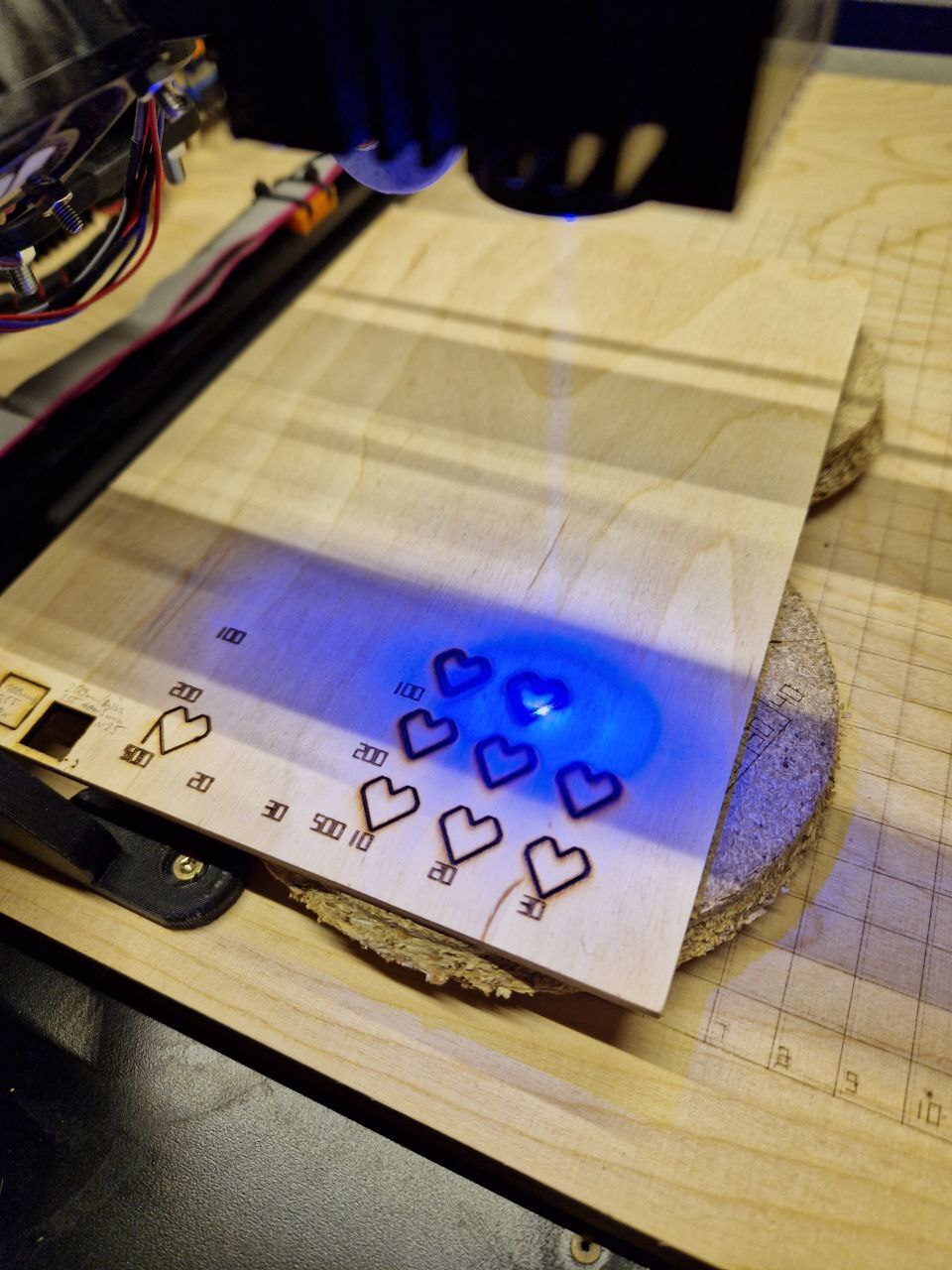
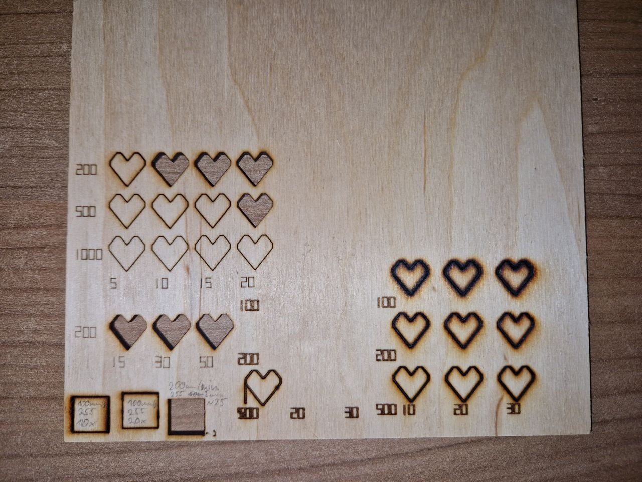
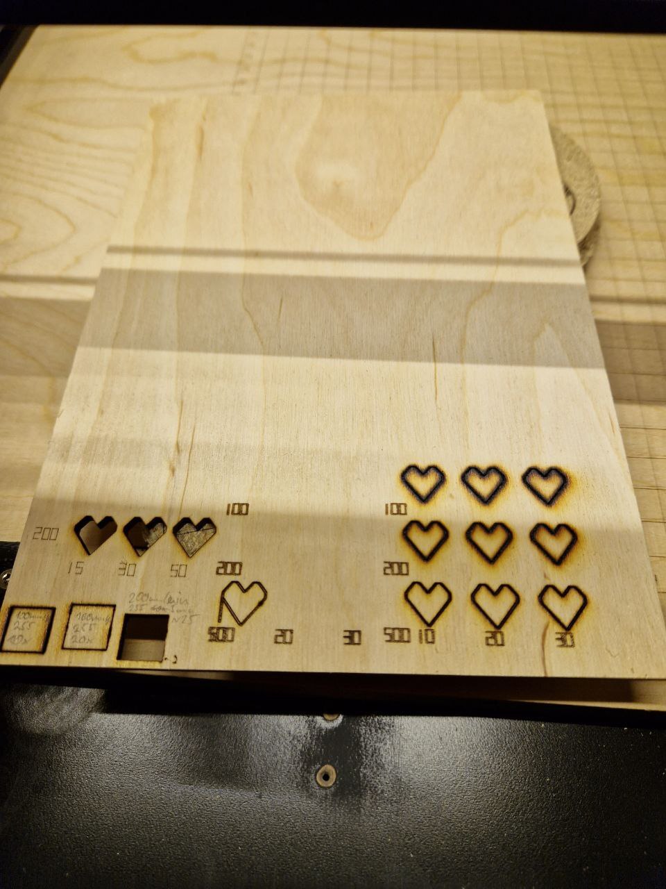
In the pictures above, the 3x3 grid of hearts on the right was made with the laser slightly out of focus. It was not able to cut through in this run, even with 30 iterations. I also still had the text not aligned properly.
The 3x1 and 3x3 runs on the left side were made after properly focussing the laser and fixing the text alignment. Here 200mm/min with 10 iterations was already enough to cut through the 3mm plywood.
Cutting Tests
For the first 'real' test I decided to cut the assembly jig for the Pagoda antenna by Maarten Baert. The files are available in dxf and svg format. I was able to easily import the svg file in LaserGRBL to create G-Code, afterwards converting it to the proper format using my script described above.
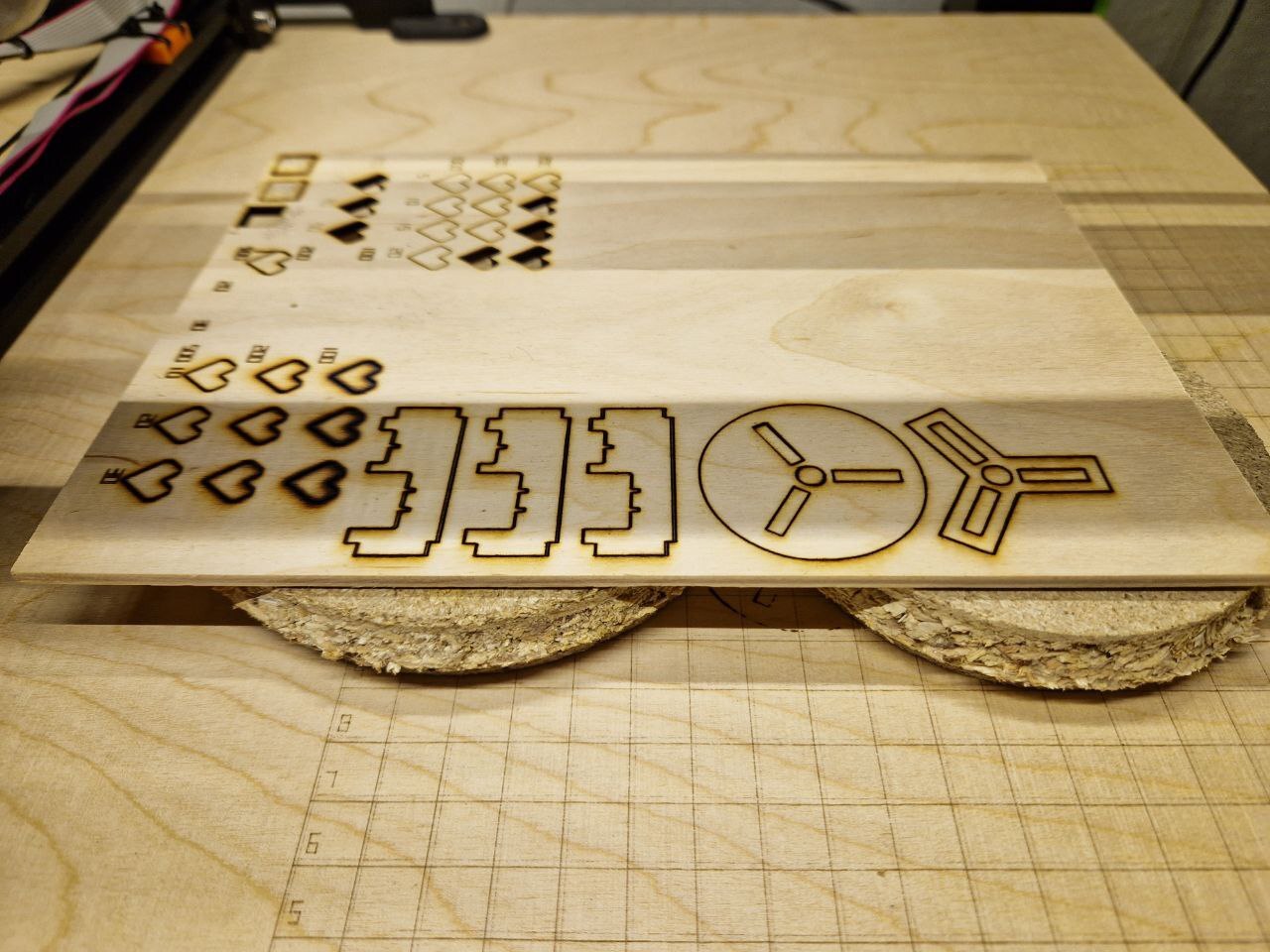
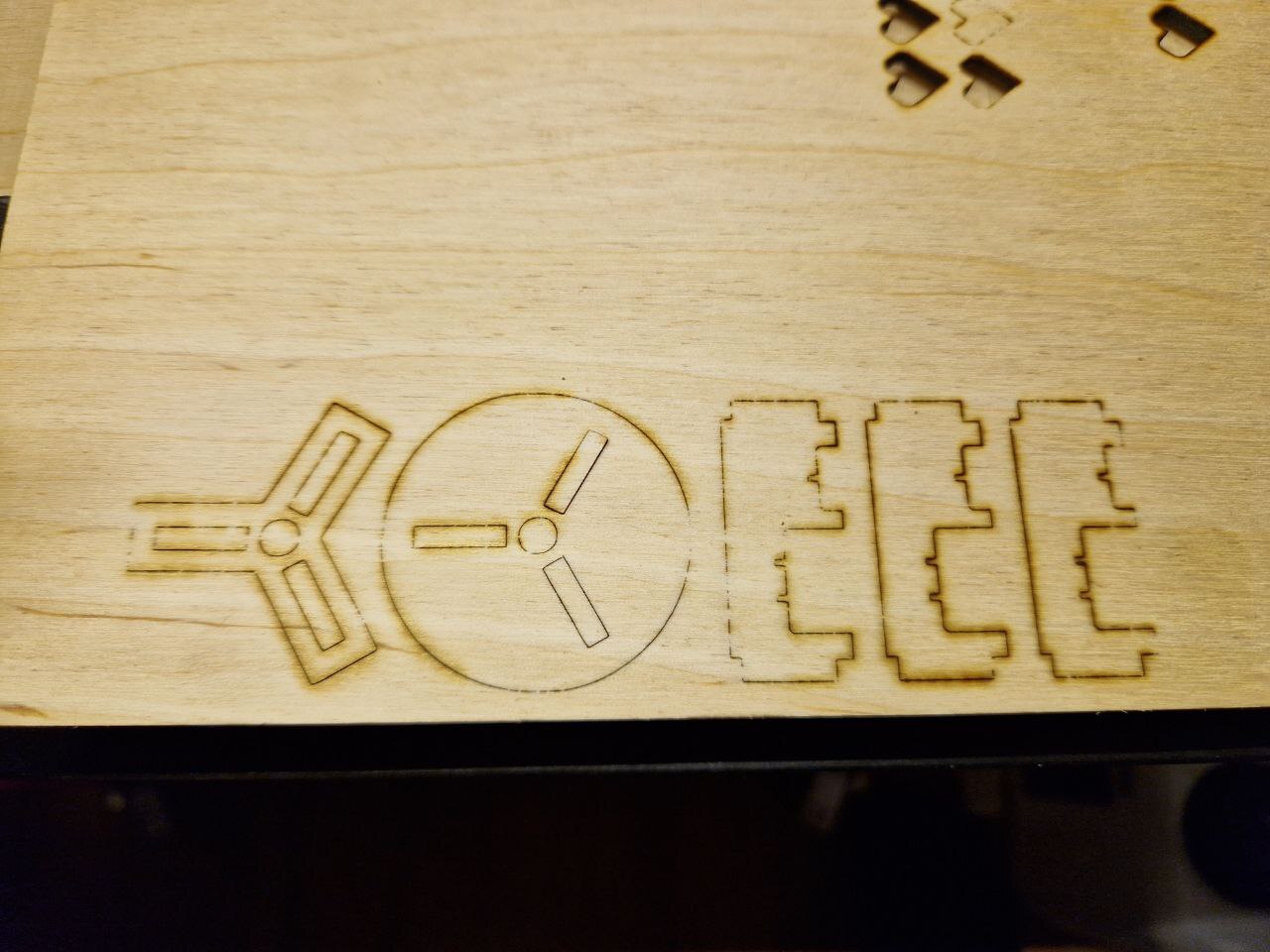
As in one of my previous tests I used 200mm/min with 10 iterations. But this was not quite enough to get the parts out easily. In hindsight I should have used at least 15 iterations. But the result was still usable, even with only 10 iterations.
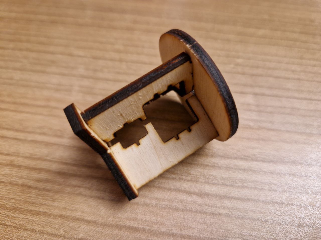
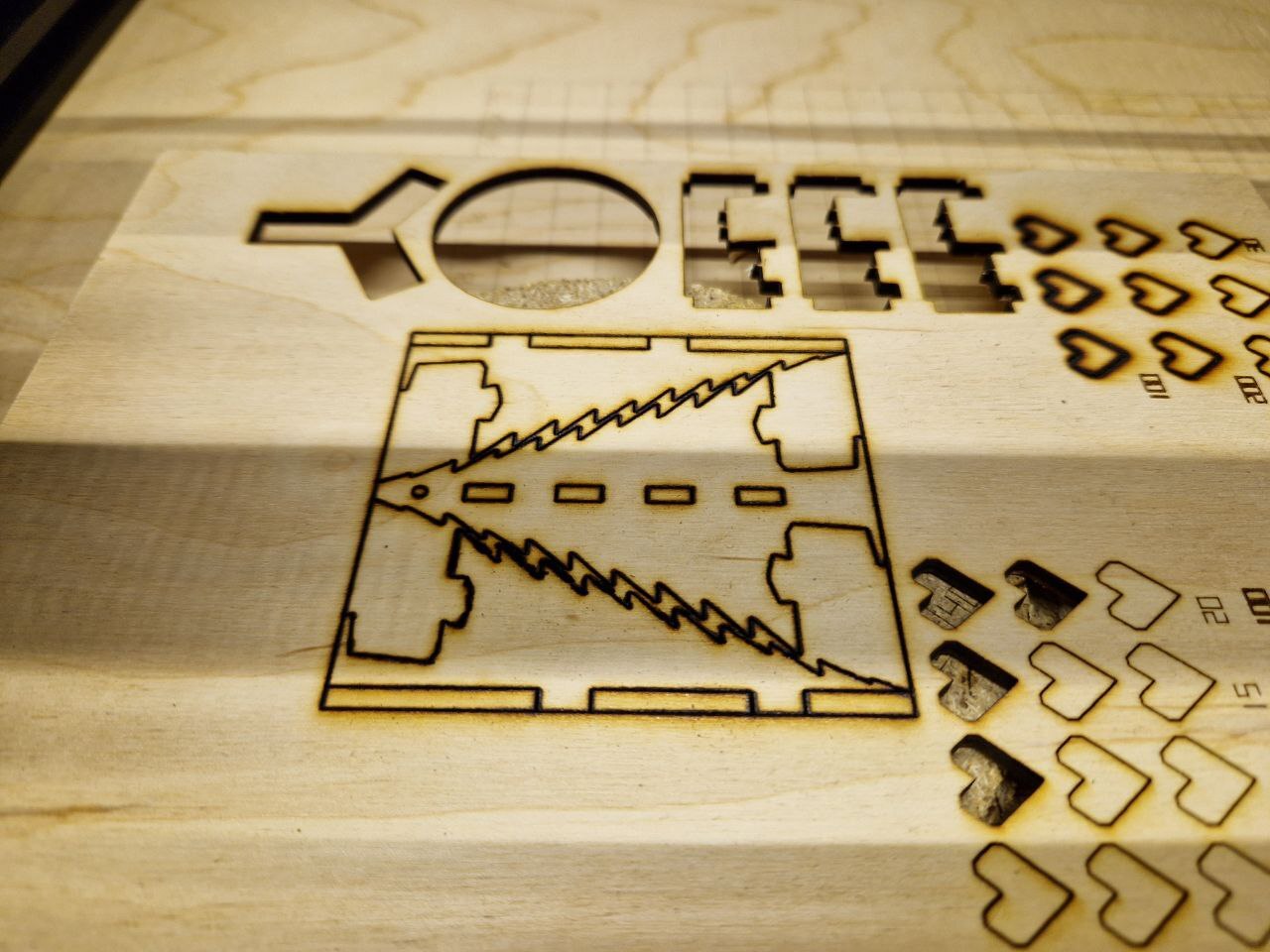
Next my SO requested some christmas decoration, so I decided to attempt to cut this Christmas Tree Ornament by TomKeddie on Thingiverse.
It is made for 4.8mm plywood, so I scaled it down by a factor of 3.0 / 4.8 = 0.625.
The design comes as a dxf file, so I imported that in Inkscape and then exported an svg file from that.
This I then imported in LaserGRBL, generated G-Code and converted that using the script above.
As you can tell from the second video, what should be single continuous lines has instead sometimes been split up into many small path segments, which LaserGRBL is cutting in non-optimal ordering. I have not yet found a way to easily clean these paths up.

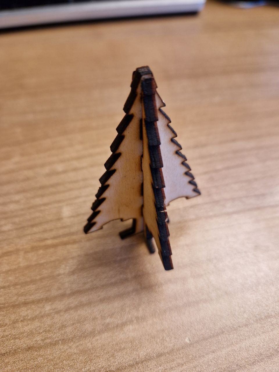
The end-result does not seem to be really affected by this however, although with 200mm/min and 15 iterations the parts were not removable as easily as I hoped. So I think I either have to adjust the focus better or go up to 20 iterations for the 3mm birch plywood.
Future Improvements
I didn't expect it to be this bad, but cutting wood really produces a noticeable amount of smoke and the smell of burnt wood. So in the long run I will have to add some kind of air filtration system to my Ikea Lack tower. Also I now better understand the need for Air Assist on laser cutters. My small fans don't help much in keeping the light-path free of smoke and soot. But I will hopefully get away with running it for a while without these additions.
Another obvious improvement is the addition of a Raspberry Pi and a Webcam, to allow remote monitoring of long-running jobs. I also came across the LaserWeb project which seems to be similar in spirit to OctoPrint for 3D printers, but also with the ability of processing vector and bitmap files from within the web interface. This would be a very useful addition and solve a lot of the software workflow problems illustrated above. Also theres more than enough room left on my base plate for a SBC.
Cutting Parameters
Here are the results of all cutting tests I've made up to now. I will update this table as soon as I gather new data 🧑🔬
| Type | Material | Thickness (in mm) |
Power (in W) |
PWM (out of 255) |
Speed (in mm/min) |
Iterations | Remarks | Date |
|---|---|---|---|---|---|---|---|---|
|
|
|
|
|
|
|
|
|
|
| Plywood | Birch | 3 | 2.5 | 255 | 200 | 10 | Difficult to remove. | 2022-11-24 |
| Plywood | Birch | 3 | 2.5 | 255 | 200 | 15 | Easily removable. | 2022-11-24 |
| Plywood | Birch | 3 | 2.5 | 255 | 200 | 20 | Freely fell out. | 2022-11-24 |
|
|
|
|
|
|
|
|
|
|
| Plywood | Birch | 3 | 2.5 | 255 | 500 | 20 | Difficult to remove. | 2022-11-24 |
| Plywood | Birch | 3 | 2.5 | 255 | 200 | 15 | Difficult to remove. | 2022-11-25 |
More Pictures